
User manual

REFERENCE AIR
CONNECTION
REFERENCE
AIR
SET
FLOW METER
INSTR.
AIR
IN
LEAK TIGHT
VALVES
2 SCFH
5 SCFH
PROBE
(END VIEW)
CALIBRATE
IN-PLACE
FITTING
CHECK
VALVE
REG
8.0%
O
2
0.4%
O
2
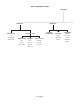
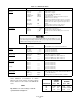
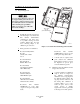
PROBE CALIBRATION GAS FITTING HAS A SEAL CAP THAT MUST
BE IN PLACE AT ALL TIMES EXCEPT DURING CALIBRATION.
NOTE:
7
300
1
3
IB-106-300NFX
3-10
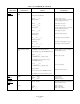
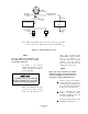
For optimum accuracy, this calibration
should be run with the process at normal
temperature and operating conditions.
Figure 3-2. Typical Calibration Setup
NOTE
check valve, Rosemount P/N
The probe calibration gas fitting has a seal
next to the calibration gas
cap which must be in place at all times
connection on the probe to prevent
except during calibration.
breathing of the line with the
In addition to the precision condensation and corrosion.
calibration gas mixtures, clean, dry,
oil-free instrument air should be
NOTE
used for calibration.
When the calibration gas line flowing as in normal operation.
exceeds 1.8 m (6 ft) in length
from the leak tight valves, a 3
Refer to paragraph 3-9d of this
6292A97H02, should be installed
process gas and subsequent gas
Only set the test gas flowmeter upon initial
installation and after changing the diffusion
element. A slightly lower test gas flow rate
may indicate a plugged diffusion element.
2
Set the test gas pressure regulators
and the flow meter for a flow of
5 scfh at (20 psig) 138 kPa for both
gases. The reference gas should be
section for Manual (Semi-
automatic) Calibration setup and
procedure using the IFT.
4
Test gases will be switched on and
off using the shutoff valves.