
User Guide
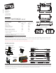

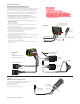


Diagram #1
Diagram #3
One Pickup
One Volume
Diagram #4
One Pickup
One Volume
One Tone
Diagram #2
Diagram #5
Installation Instructions:
EMG Models: MARTY FRIEDMAN MF - SET
General Notes:
Every attempt has been made to make this a solderless installation.
There are some instances where this is not possible;
1) If your instrument uses the long panel output jack, soldering will be required
2) Instruments with two pickups may need soldering to the selection
switch in some installations.
If you are installing only one pickup use the instructions on this page.
If you are installing two pickups go to page 3 and begin there.
VOLUME250K 500K
B159A
VOLUME250K 500K
B159A
MF SET INSTRUCTIONS Page 2
Attaching the bridge ground wire
6) Refer to Diagram #5.
As mentioned on page 1, it is common to “ground” (earth)
the strings on guitars that have passive pickups.
Included with the system is a black wire with a single black
connector attached. Also included is an IDC connector for
connecting the two wires together. Insert the bridge ground wire,
and the connector wire into the IDC connector, crimp the connector
with a pair of pliers until it snaps and this will connect the two wires.
You don’t need to strip the insulation from the wires.
Push the black connector onto terminal 2 (GND),
or any other terminal marked GND of the volume control.
This will ground the strings to the system.
T
S
OUTPUT
T
S
OUTPUT
GREEN AND SHIELD
RED
BLACK AND WHITE
EMG-HZ Wire Order:
Pin 1 Green (GRN)
Pin 2 White (WHT)
Pin 3 Braid (GND)
Pin 4 Red (RED)
Pin 5 Black (BLK)
250K 500K
B160A
TONE
EMG
B159A
VOLUME250K
NECK
VOLUME
STRING GROUND WIRE
COMING FROM THE BRIDGE
BLACK WIRE INCLUDED
WITH CONNECTOR
1
2
3
4
5
6
Installation (One Pickup Guitars):
1) Plug the pickup cable onto the EMG Pickup header as shown
in Diagram #1 and route the cable to the control cavity.
If the cable is too long, wind up the excess and keep it
under the pickup if possible.
Diagram #2 shows the factory pre-wired cable. The Green
wire and shield are pre-wired to Pin 1 and the Red wire is
pre-wired to Pin 2. The Red wire is the signal output from
the pickup. The White and Black wires are wired together and
covered with shrink tubing. This is standard humbucking series
wiring.
Master Volume control only
2) Refer to Diagram #3.
Plug both the Pickup cable and the output
cable onto the Volume control as shown, then go to step 4.
Master Volume and Tone control
3) Refer to Diagram #4.
Plug the Pickup cable onto the Volume
control as shown. Plug a coax cable from the Volume control
to the Tone control. Plug the output cable onto the tone
control as shown.
4) Connect the wires of the output cable to the output jack by
pushing the connectors on as shown.
WHITE wire to the TIP (T) contact,
BLACK wire to the SLEEVE (S) contact
We suggest that you plug in the instrument and
test it before closing the control cavity.
FROM PICKUP
MASTER
TONE
OUTPUT CABLE
OUTPUT CABLE
FROM PICKUP
MASTER
VOLUME
MASTER
VOLUME
TO STRING GROUND
SEE DIAGRAM #5
TO STRING GROUND
SEE DIAGRAM #5
CLOSED
CRIMP
(INSERT WIRES)