
User Guide
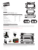


BRIDGE PICKUP INPUT
NECK PICKUP INPUT
OUTPUT
PLUG IN
LIKE THIS!
TIP
RING
SLEEVE
Diagram #7
FROM TONE
OR VOLUME
NOT USED
Installation Instructions:
EMG Models: MARTY FRIEDMAN - MF SET
MF SET INSTRUCTIONS Page 3
T
S
OUTPUT
****Tips and Tricks****
****Tips and Tricks****
Start your installation by:
Start your installation by:
1) Remove the strings
1) Remove the strings
2) Remove any existing Pickups and controls
2) Remove any existing Pickups and controls
(remember the order and function of each control)
(remember the order and function of each control)
3) Determine a good spot for the Pickup Buss and make sure the
3) Determine a good spot for the Pickup Buss and make sure the
cable or wires from the selection switch will reach the Pickup Buss,
cable or wires from the selection switch will reach the Pickup Buss,
4) Install the EMG Volume and Tone Controls and tighten them in.
4) Install the EMG Volume and Tone Controls and tighten them in.
5) Then install the pickups keeping any excess cable under the pickup
5) Then install the pickups keeping any excess cable under the pickup
rather than in the control cavity.
rather than in the control cavity.
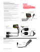
2 Pickups / Toggle Select Switch / Master Volume and Tone
NECK PICKUP
BRIDGE PICKUP
OUTPUT TO MASTER VOLUME
Diagram #6b
2 Pickups
Toggle Style Select Switch
Master Volume & Master Tone
MASTER
TONE
FROM NECK PICKUP
FROM BRIDGE PICKUP
MASTER
VOLUME
OUTPUT CABLE
250K 500K
B160A
TONE
EMG
6
5
4
3
2
1
Soldering to the 152B Panel Jack:
If your instrument has a long Panel Jack like the one below
you will have to solder the output cable as shown.
Ground (Black) to the Sleeve
Signal (White) to the Tip
Battery Negative (Black) to the Ring
1) Install the Pickups and route the Pickup cables to the control cavity.
If the cables are too long, wind up the excess and keep it under the pickup.
2) Mount the Volume and Tone controls into the body.
Plug both Pickup cables onto the Pickup Buss (BLACK Shroud) as shown,
Refer to Diagram #6a
Bridge Pickup to Position 1
Neck Pickup to Position 2.
3) Plug a coax cable from the Pickup Buss (Position 3) to the Master Volume
control as shown in Diagram #6b.
4) Plug a coax cable from the Master Volume to the Master Tone as shown.
5) Strip the insulation from the switch wires and Insert them into the GREEN
Terminal Block and tighten the screws with a small screwdriver.
The Bridge pickup goes to the BR Terminal
The Neck pickup goes to the NK Terminal
The Output of the switch goes to the O Terminal
If there is a ground wire coming from the switch, insert it into one of the black
terminals on the terminal block.
6) Plug the output cable onto the Master Tone control and connect the output
wires to the output jack by pushing the connectors on as shown.
WHITE wire onto the TIP (T) contact,
BLACK wire onto the SLEEVE (S) contact
We suggest that you plug in the instrument and test it before closing the
control cavity.
Installation (Two Pickup Guitars with Selection switch):
Guitars with two pickups and a selection switch will use the EMG B245 Pickup Buss.
The Pickup Buss is a convenient way to wire your guitar without soldering.
There is a separate sheet attached to these instructions that describes the
Pickup Buss in detail. Since you are installing passive EMG-HZ Pickups the RED
Shroud of the B245 Pickups Buss will not be used. It is for battery power.
TO STRING GROUND
SEE DIAGRAM #5
Diagram #6a