
User Guide

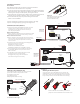

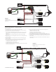


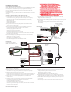
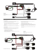

Diagram #2
One Pickup
One Volume
Diagram #3
One Pickup
One Volume
One Tone
TIP
RING
SLEEVE
Diagram #4
FROM TONE
OR VOLUME
General Notes:
Every attempt has been made to make this a solderless installation.
There are some instances where this is not possible;
1) If your instrument uses the long panel output jack and you had passive pickups
you will need a new stereo output jack, the Switchcraft 152B is recommended.
Soldering to the new jack will be required, see diagram #4 below.
2) Some instruments may already have a battery holder installed and in that case
soldering may be required to the battery buss, see diagram #5 below.
3) Instruments with two pickups may need soldering to the selection
switch in some installations.
If you are installing only one pickup use the instructions on this page.
If you are installing two pickups go to page 3 and begin there.
Installation Instructions:
57 INSTRUCTIONS Page 2
VOLUME
B122rH
VOLUME
B122rH
TONE
B124rH
BATTERY
NEG (-)
RED to BATTERY BUSS
Soldering to the 152B Panel Jack:
If your instrument has a long Panel Jack like the one below
you will have to solder the output cable as shown.
Ground (Black) to the sleeve
Signal (White) to the Tip
Battery Negative (Black) to the Ring
- 9V +
Diagram #1
Insert the plug onto the 3 pin header
of the pickup as shown above.
Note the orientation arrow.
Installation (One Pickup Guitars):
1) Plug the pickup cable onto the EMG Pickup header as shown
in diagram #1 and route the cable to the control cavity.
If the cable is too long, wind up the excess and keep it
under the pickup if possible.
Master Volume control only
2) Refer to diagram #2. Plug both the Pickup cable and the output
cable onto the Volume control as shown, then go to step 4.
Master Volume and Tone control
3) Refer to diagram #3. Plug the Pickup cable onto the Volume
control as shown. Plug a coax cable from the Volume control
to the Tone control. Plug the output cable onto the tone
control as shown.
4) Connect the wires of the output cable to the output jack by
pushing the connectors on as shown.
WHITE wire to the TIP (T) contact,
BLACK wire to the SLEEVE (S) contact
BLACK Battery Negative wire to the RING (R) contact.
5) Using the battery buss, insert the RED wire of the pickup,
and the battery RED wire. Extra pins can be used for
EMG Accessories.
6) Put the battery in the insulating foam piece provided
and place it securely in the control cavity.
We suggest that you plug in the instrument and
test it before closing the control cavity.
Diagram #5
Solder the RED wire from the Battery Holder and/or
pickups and re-insert the Header into the insulation cover
1
3
Soldering to the battery buss:
If your instrument has an older EMG Pickup you can solder the
pickup RED wire to the buss. Simply use some needle nose pliers,
pull out the V+ header and solder the RED Wire from the pickup(s)
to any of the pins and then re-insert the header into the housing.
2
MASTER
VOLUME
FROM PICKUP
T
R
S
BATTERY
NEG (-)
RED
RED
BATTERY
BUSS
T
R
S
MASTER
TONE
FROM PICKUP
BATTERY
NEG (-)
RED
RED
BATTERY
BUSS
OUTPUT CABLE
OUTPUT CABLE
MASTER
VOLUME
- 9V +
- 9V +