
User Guide
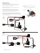
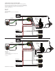
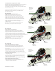

Diagram #6
Volume Control
Tone (Passive)
AB Control
SEND
RETURN
AB (Afterburner) Page 4
3 Pickup Guitars using a selection switch:
Diagrams #6 and #7 show a typical installation with a Volume/Tone/AB in a
“daisy-chain” series wiring. The diagrams yield the same
results. The diagrams have been edited to show the input, output,
and power (9V+). The pickup inputs, battery, and “ring”contact to the jack
have been omitted for clarity.
All diagrams show the B161 5-Position switch buss. To learn more
about the B161 5-Position switch Buss, go to the EMG Website:
http://www.emgpickups.com.
Refer to Diagram #6
Volume / AB Control / Passive Tone Control
The AB Control and the Tone control can be in different
positions on the pickguard, but the wiring remains the same.
1) Plug a coax cable from the output switch to the Volume control.
2) Plug a coax cable from the Volume control to the Tone control.
3) Plug a coax cable from the Volume control to the input of the AB.
Be sure to reverse the connector on the input of the AB as shown.
4) Plug the output cable from the AB to the output jack.
5) Plug the Red wire from the AB to one of the supply pins on the
B161 Switch Buss.
Be sure the 3 shunts are installed on the bypass header of the
B161 switch or you won’t get any output from the guitar.
Refer to Diagram #7
Volume / VLPF Active Tone / AB Control
The AB Control and the VLPF Tone control can be in different
positions on the pickguard, but the wiring remains the same.
1) Plug a coax cable from the output switch to the Volume control.
2) Plug a coax cable from the Volume control to the input of the VLPF.
Be sure to reverse the connector on the input of the VLPF as shown.
3) Plug a coax cable from the output of the VLPF to the input of the AB Control.
4) Plug the output cable from the AB Control to the output jack.
5) Plug the Red wire from the AB to one of the supply pins on the
B161 Switch Buss.
Be sure the 3 shunts are installed on the bypass header of the
B161 switch or you won’t get any output from the guitar.
Refer to Diagram #8
Volume / SPC (Bridge Pickup only) / AB Control
Diagram #8 shows 2 active controls installed: The SPC and AB.
This installation is unique because it takes advantage of the
send/return feature of the B161 switch by using the SPC Control
only on the Bridge Pickup, while using the AB Control at the output of
the instrument.
1) Plug a coax cable from the switch output to the Volume control.
2) Plug a coax cable from the Volume control to the input of the AB.
Be sure to reverse the connector on the input of the AB as shown.
Send and Return to the SPC Control
3) Plug a coax cable from the Bridge Pickup Send pins on the Select switch
to the input of the SPC.
Be sure to reverse the connector on the input of the SPC as shown.
4) Plug a coax cable from the output of the SPC to the Bridge pickup
Return pins on the Select Switch.
Be sure to remove the blue shunt on the B161 switch for the bridge
pickup or the SPC Control will have no effect.
Plug the output cable from the AB to the output jack.
5) Plug the Red wires from both the SPC and AB to the extra 9V+
supply pins on the B161 Switch Buss.
Diagram #8
Volume Control
Tone (Active VLPF)
AB Control
Diagram #7
Volume Control
Tone (Active VLPF)
AB Control
VOLUME CONTROL
AB CONTROL
SPC
CONTROL
TO OUTPUT JACK
NOTE:
REVERSED
CONNECTOR
VOLUME CONTROL
AB CONTROL
TONE CONTROL
(PASSIVE)
TO OUTPUT JACK
VOLUME CONTROL
AB CONTROL
VLPF
ACTIVE TONE
TO OUTPUT JACK
NOTE:
REVERSED
CONNECTOR
NOTE:
REVERSED
CONNECTOR
NOTE:
REVERSED
CONNECTOR
NOTE:
REVERSED
CONNECTOR
REMOVE
BLUE SHUNT