
Instruction manual

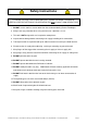
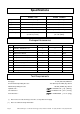
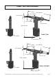
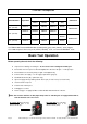
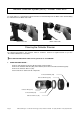
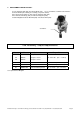
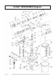
Table Of Contents
- Introduction
- Safety Instructions
- Specifications
- Packaged Accessories
- Tool Requirements
- ProSet® 2500 Tool Dimensions
- Common Nosepieces
- Basic Tool Operation
- ProSet® 2500 Front End Service
- Mandrel Collection System (MCS) – ProSet® 2500 MCS
- Cleaning the Collector Silencer
- Tool Assembly Torque Requirements
- ProSet® 2500/2500MCS Diagram
- ProSet® 2500 Parts List
- Hydraulic Oil Charging Procedure
- Maintenance
- Safety Data
- Troubleshooting
- EC Declaration of Conformity
- Conforms to the following standards:
- Signed: ____________________________________
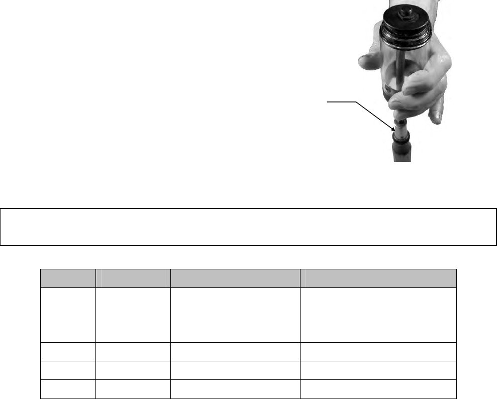
2. RE-ASSEMBLE THE COLLECTOR :
Secure Collector End (104) to Collector Body (101). Use a screwdriver or similar tool to hold the
Collector End in place during re-assembly (see picture below).
Place the Collector Silencer (103) onto the Collector End (104).
Place Collector End Cap (105) on Collector Body End (104).
Install and tighten Collector End Nut (106) on Collector End (104).
Screwdriver
Tool Assembly Torque Requirements
Item Part No. Description Torque Value
1
119
120
PRN614
PRN414
PRN514
Nosepiece 6 size
Nosepiece 4 size
Nosepiece 5 size
60 – 65 in-lbs (6.8 – 7.3 N-m)
51 DPN239-053 Sleeve Lower 35 - 39 ft-lbs (47 - 53 N-m)
61 DPN239-063 Sleeve Lock Nut 31 - 35 ft-lbs (42 - 48 N-m)
88 DPN907-003 Socket Head Cap Screw 46 - 51 in-lbs (5.2 – 5.8 N-m)
See exploded Tool Diagram
Emhart Teknologies - 50 Shelton Technology Center, Shelton CT 06484 - Tel. (203) 924-9341 - Fax (800) 225-5614 Page 9