INSTALLATION, OPERATION AND MAINTENANCE MANUAL EMI AMERICA SERIES MULTI-ZONE LIMITED RANGE HEAT PUMP CONDENSING UNITS S2HA & T2HA HEAT PUMPS Nominal Circuit Capacities: 9,000 12,000 18,000 & 24,000 Btuh units. S2HA Multi-Zone T2HA Multi-Zone Enviromaster International LLC 5780 Success Dr. Rome, NY 13440 www.enviromaster.com An ISO 9001-2000 Certified Company P/N# 240006458 Rev. 1.
EMI AMERICA SERIES MULTI-ZONE HEAT PUMP CONDENSING UNITS INSTALLATION, OPERATION AND MAINTENANCE MANUAL P/N 240006458, Rev. 1.1 [04/07] This manual is intended as an aid to qualified service personnel for proper installation, operation, and maintenance of these EMI America Series multi-zone heat pump condensing units. Read the instructions thoroughly and carefully before attempting installation or operation.
EMI AMERICA SERIES MULTI-ZONE HEAT PUMP CONDENSING UNITS SYSTEM OPTIONS DESCRIPTION • Sea Coast Style Coated Coils / Copper-Copper coils • Wind Baffles - Louvers• EMI offers the finest multi-zone heat pump outdoor units in the ductless split market, the S & T series (S2HA, T2HA, T3HA & T4HA) Condensing Units.
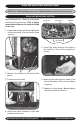
S2HA INSTALLATION INSTRUCTIONS NOTE: For T2HA installation refer to the T2HA Installation Instruction in this manual. S2HA UNIT MOUNTING SECTION Side discharge unit allows for permanent mounting through the feet. This is highly recommended due to the vertical design of the unit. Accumulator Compressor Capacitor 1. Loosen the screws on left and right sides of the front panel. (Do not remove these screws.) Filter Driers Lag Bolts 5.
S2HA ELECTRICAL WIRING INSTALLATION SECTION ! DANGER ! The EMI America Series condensing unit must: • Be connected to a properly grounded electrical supply with the proper voltage as stated on the rating plate. 3. Use only HACR type breakers or time delay fuses. Select the wire size according to the ampacity rating. 4. To access electrical connections and wiring diagram: a) Remove the screws on the side panel adjacent to the back panel.
S2HA ELECTRICAL WIRING INSTALLATION SECTION Inside electrical access panel. Note: Refer to the units’ wiring diagram for all wiring. Wire Diagram 8. Check wiring diagram for the required number of low voltage wires to be run between indoor and outdoor sections. Low Volt High Volt Plastic Edge Guards 9. Connect the 24 Volt wiring matching color to color. Refer to the wiring diagram on the inside panel of the condenser, and also refer to the wiring diagram on the indoor unit.
T2HA INSTALLATION INSTRUCTIONS NOTE: For S2HA installation refer to the S2HA Installation Instruction in this manual. After the T2HA unit is positioned on the concrete slab or platform (refer to the Site Preparation in the front of this manual) the T2HA is ready for installation: 1. Remove the screw on the back panel. ELECTRICAL WIRING 1. All electrical wiring must be run according to NEC and local codes. 2.
T2HA INSTALLATION INSTRUCTIONS ELECTRICAL WIRING 5. With a screwdriver punch out and remove the knock-outs in the low & high Volt electrical connection box. Low Volt High Volt Knock-out Note: Power should be run to a weather proof disconnect box usually within 3 feet of the unit. 8. Check wiring diagram for the required number of low voltage wires to be run between indoor and outdoor sections. 6.
S2HA & T2HA REFRIGERANT PIPING INSTALLATION SECTION NOTE: Refrigerant Piping Installation for both the S2HA & T2HA models. pressure readings. The following precautions should be made: • Be certain no burrs remain on the fittings.
S2HA & T2HA REFRIGERANT PIPING INSTALLATION SECTION 1. Clean the ends of tubing and insert into fittings. 2. Protect the valves by wrapping with a wet rag "heat sink" before brazing. T2HA Shown 5. Verify that the correct piston for the system match is in place, refer to the air handler Installation Instructions. 6. Refer to the indoor air handler Installation Instructions for any specific details regarding the connection of tubing. Connect and braze tubing into the indoor air handler. 7.
S2HA & T2HA REFRIGERANT PIPING INSTALLATION SECTION S2CA Shown T2HA Shown Refer to Refrigerant Charge Table for specified line charge. nt igera Refr 22 R Note: Charging should be done with a dial-a-charge or weighed in with a scale. 9. Once certain of a good evacuation and leak free joints, back-seat the valves (counter-clockwise) to open and allow factory charge to fill lines and indoor unit. 10.
S2HA & T2HA REFRIGERANT PIPING INSTALLATION SECTION S2HA & T2HA REFRIGERANT CHARGE TABLE Circuit Capacity Btuh Evaporator Pairing Line Chg/ft Line Length Line Adjust Factory Charge Total Charge 9000 WLHA09 CAHB12 0.25 oz 10 ft 25 ft 50 ft 3 oz 6 oz 13 oz 42 45 oz 48 oz 55 oz 12000 WLHA12 CAHB12 0.25 oz 10 ft 25 ft 50 ft 3 oz 6 oz 13 oz 46 49 oz 52 oz 59 oz 18000 WLHA24 CAHB24 0.56 oz 10 ft 25 ft 50 ft ** 6 oz 14 oz 28 oz ** 80 86 oz 94 oz 108 oz 24000 WLHA24 CAHB24 0.
MULTI-ZONE HEAT PUMP FIELD CHARGING Cooling Cycle 9,000 Btuh Circuit Cooling Cycle 12,000 Btuh Circuit with EMI’s-WLHA09 or CAHB12 (���������� ��� ��������������� ��������������������� ��� �������������������� �������������������� ��� with EMI’s-WLHA12 or CAHB12 (���������� ��� ��� ��� ��� ��� ��� �� �� �� �� ����� ����� ����� �� �� �� �� ����� ����� ����� �� �� �� �� �� ��� ���� ��� ��� ��� ���� ������������������ ��� ������������������������� ������������������������� ��� ��� �
MULTI-ZONE HEAT PUMP FIELD CHARGING Cooling Cycle 24,000 Btuh Circuit Cooling Cycle 18,000 Btuh Circuit with EMI’s-WLHA24 or CAHB24 (���������� with EMI’s-WLHA24 or CAHB24 (���������� ��� ��� �������������������� ��������������� ��������������������� ��� ��� ��� ��� ��� �� �� �� ����� ����� ����� �� �� �� ����� ����� ����� �� �� �� �� �� ��� ���� ��� ��� ��� ���� ������������������ ��� ������������������������� �� ������������������������� ��� ��� �� ��������������� ��������������
MULTI-ZONE HEAT PUMP FIELD CHARGING Heat Cycle 12,000 Btuh Circuit Heat Cycle 9,000 Btuh Circuit with EMI WLHA09 or CAHB12 (���������� �������������������� ��������������� ��� ��� ��� ������������������� ��� ��� ��� ��� ��� ����� ����� ����� �� �� �� �� �� ����� ����� ����� �� �� �� �� ���������������������� ���������������������� ��� ��� �� ��������������� ��� ������������������� �������������������� ��� with EMI WLHA12 or CAHB12 (���������� �� �� �� � ���� ��� ��� ��� ��� �� ��
MULTI-ZONE HEAT PUMP FIELD CHARGING Heat Cycle 24,000 Btuh Circuit Heat Cycle 18,000 Btuh Circuit with EMI’s-WLHA24 or CAHB24 (���������� with EMI’s-WLHA24 or CAHB24 (���������� ��������������� �������������������� ��� ��� ��� ������������������� ��� ��� ��� ��� ��� ����� ����� ����� �� �� �� �� �� ����� ����� ����� �� �� �� �� ���������������������� ���������������������� ��� ��� �� ��������������� ��� ������������������� �������������������� ��� �� �� �� � ���� ��� ��� ��� ���
S2HA & T2HA REFRIGERANT PIPING INSTALLATION SECTION FIELD CHARGING NOTE: If operating superheat is more than 5°F above the chart value, add refrigerant. If below the chart value remove refrigerant. If below the limit line, remove refrigerant. Example (Using the 12,000 Btuh cooling chart): 1. Suction pressure is 65 psi. which equals 38° F on The R-22 Scale of the LowSide Gauge. 2. Suction line temperature taken at the unit is 70° F. 70° F minus 38° F equals 32° F superheat. 3.
START-UP AND TROUBLESHOOTING TEST PROCEDURE The Test Unit Performance Data sheet below is provided for use by a qualified service professional. In order for our Technical Service Department to better serve you, please complete and have this information ready when calling. Make sure to include the Model Number, Serial Number, Date of Installation. Call our Technical Support Department @ 1-800-228-9364.
MULTI-ZONE CONDENSER SEQUENCE OF OPERATION EMI America Series multi-zone heat pump condensers are designed to operate with EMI America Series indoor air handlers. Both the condenser (outdoor unit) and evaporator (indoor unit) have a high Volt service connection. Each is to be independently connected to the electrical service panel. (See the unit name plate for the correct breaker type and size). The outdoor and indoor units are also connected to each other through a low Volt interconnect wiring.
MULTI-ZONE CONDENSER SEQUENCE OF OPERATION When the outdoor temperature falls below 35°F, compressor operation will cease. At that point the unit will switch on the indoor units electric heater to assume the heating demand, (second stage of heat). Note: For full operation the indoor unit must have an electric heater. LOW VOLT INTERCONNECT DIAGRAMS CAHB W/ OPTIONAL ELECTRIC HEAT, LOW VOLTAGE INTERCONNECT DIAGRAM WL HA Wall unit Heat P ump A pplic ations I.D. UNIT O.D.
S2HA DIMENSIONS AND SPECIFICATIONS NOTE: All EMI products are subject to ongoing development programs so design and specifications may change without notice. 15” 38” Easy access interconnects on back of unit 44” 1/2” Diameter Lag Holes Front of unit 3.00” Electrical connections 12.44” 28.74” 4.63” 4.63” S2HA ELECTRICAL SPECIFICATIONS MODEL VOLTS/HZ/PHASE (1) FAN COMPRESSOR 1 COMPRESSOR 2 TOTAL AMPS MIN. CIR. HACR AMPS BRKR (2) RLA HP RLA LRA RLA LRA 9900 208-230/60/1 1.8 0.33 3.
S2HA SYSTEM PERFORMANCE WLHA S2HA S2HA / WLHA SYSTEM PERFORMANCE MODEL COOLING HEATING S2HA (Outdoor) Indoor Units Btuh SEER SHR EER Btuh C.O.P. 9900 WLHA09 + WLHA09 18,600 13.0 .80 12.2 16,000 3.3 2200 WLHA12 + WLHA12 22,600 13.0 .72 11.9 20,000 3.3 9200 WLHA09 + WLHA12 20,600 13.0 .76 12.0 18,000 3.
T2HA DIMENSIONS AND SPECIFICATIONS NOTE: All EMI products are subject to ongoing development programs so design and specifications may change without notice. INTERCONNECTING TUBING SPECS T2HA, T3HA, & T4HA models: SOUND & WEIGHT DATA Model Sound Weight Nominal Circuit Capacity Maximum Maximum Length Lift Liquid Line OD Suction Line OD dBA Lbs.
T2HA DIMENSIONS AND SPECIFICATIONS WLHA T2HA Top Discharge WLHA / T2HA SYSTEM PERFORMANCE DATA Model Cooling Heating T2HA Outdoor Condenser Indoor Air Handler Btuh SEER SHR EER Btuh COP 8800 WLHA24 + WLHA24 36000 13 0.72 12.4 29000 3.3 8400 WLHA24 + WLHA24 42000 13 0.68 12.2 34800 3.2 4400 WLHA24 + WLHA24 48000 13 0.65 12.1 40500 3.