installation, operation and maintenance MANUAL S1C/S1H Single-Zone & S2C Dual-Zone Side discharge Ductless Split System Condensing Units Straight Cool/Heat pump S1C/S1H Nominal Circuit Capacities S1C/S1H: 9,000, 12,000, 18,000, 24,000 Btuh and S1C 30-36 Btuh Cooling Only S2C Nominal Circuit Capacities: 9,000-12,000 Btuh S1C/S1H S2C Enviromaster International LLC 5780 Success Dr. Rome, NY 13440 www.enviromaster.com An ISO 9001-2000 Certified Company P/N# 240005897 Rev.
S1C/S1H Single-Zone & S2C Dual-Zone Condensing Units installation, operation and maintenance MANUAL This manual is intended as an aid to a qualified service personnel for proper installation, operation, and maintenance of EMI AmericaSeries high efficiency condensing units. Carefully read these instructions before attempting installation or operation.
CONTROLS and COMPONENTS (Factory installed or supplied) PRODUCT DESCRIPTION The AmericaSeries S1C/H and S2C condensing units are, air-cooled, vertically arranged side discharge, high efficiency units designed specifically to meet or exceed a 13 SEER rating. The S1C 9,000-36,000 Btuh and S1H 9,000-24,000 Btuh capacity condensing unit will provide cooling for a single evaporator, as identified in the "S1C Specifications and Dimensions" section on pages 23-24.
Installation Instructions System OPTIOns (cont.) void the warranty. A Field installed lowambient kit is good for operation down to 32º F. This is accomplished by cycling the condenser fan on and off, which will in turn maintain a constant low side pressure providing a steady cooling effect and keeping the air handler from frosting-up. Unit Mounting Instructions S1C is shown Side discharge unit allows for permanent mounting through the feet.
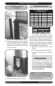
Installation Instructions ELECTRICAL WIRING Unit Mounting Instructions Continued Compressor Accumulator 1. All electrical wiring must be run according to NEC and local codes. Capacitor 2. Refer to the unit rating plate for voltage, minimum circuit ampacity and over current protection requirements. S1C Shown rating plate Filter Drier Lag Bolts 5. Insert lag bolts through the holes in the bottom of the unit and tighten to secure. 3. Use only HACR type breakers or time delay fuses.
Installation Instructions 8. Check wiring diagram for the required number of low voltage wires to be run between indoor and outdoor sections. c. Slide the side panel out to access the high/low electrical connections and wire diagram. S1C S1C Shown High Volt Low Volt plastic edge guards Low Volt Connection Note: Remove the plastic edge guards from the holes and replace with a watertight strain relief fitting (High V) and a split grommet fitting (low V) 9.
Installation Instructions ELECTRICAL WIRING Continued REFRIGERANT PIPING Interconnecting Tubing Specifications S1 MAX. Max. Liquid Suction Model Length Lift Line O.D. Line O.D. 09 100’ 35’ 1/4" 1/2" 12 100’ 35’ 1/4" 1/2" 18 100’ 35’ 3/8" 5/8" 24 100’ 35’ 3/8" 3/4" 30 100’ 35’ 3/8" 3/4" 36 100’ 35’ 3/8" 3/4" S2C TubING SPECIFICATIONS Line Sizes O.D.
Installation Instructions P-Trap Installation ricated trap may be purchased from a wholesaler or distributor however the trap should be shallow as the (3) elbow configuration. Each elbow is approximately 2 equivalent feet. One P-trap is equal to approximately 12 equivalent feet. • A P-trap is recommended when the suction riser is equal to or greater than 20 feet in height. • When the condenser is installed above the evaporator, the P-trap will help the return of oil back to the compressor.
Installation Instructions REFRIGERANT PIPING Continued 1. Clean the ends of tubing and insert into fittings. S2C S1C Shown S1C Shown 5. Attach manifold set. manifold Vaccum Pump Micron Gage 2. Protect the valves by wrapping with a wet rag "heat sink" before brazing. S1C Shown Manifold Setup For Evacuation S1C Shown 6. Evacuate line to 500 microns or less to ensure all moisture has been removed and there are no leaks. 3.
Installation Instructions COMPLETE PIPING CONNECTIONS 8. Charge to proper weight, charge based on feet of interconnect (tables starting on page 10). 9. Refer to Charts on page 12 to “fine tune” the refrigerant charge to meet your conditions. S1C Shown S2C Shown Note: Charging should be done with a dial-a-charge or weighed in with a scale. REFRIGERANT PROCESSING IMPORTANT NOTES: 1.
Installation Instructions REFRIGERANT PROCESSING continued S2C REFRIGERANT CHARGE TABLE CONDENSER EVAPORATOR PAIRING LINE CHG/FT FACTORY CHARGE S2C99 WLH09 .25 oz. 28 oz./ 28 oz. S2C22 WLH12 .25 oz. 33 oz./ 33 oz. S2C92 WLH09+WLH12 .25 oz. 28 oz./ 33 oz. S2C99 CAC12 .25 oz. 28 oz./ 28 oz. S2C22 CAC12 .25 oz. 33 oz./ 33 oz. S2C92 CAC12 .25 oz. 28 oz./ 33 oz. S2C99 UNH09 .25 oz. 28 oz./ 28 oz. S2C22 UNH12 .25 oz. 33 oz./ 33 oz. S2C92 UNH09+UNH12 .25 oz. 28 oz./ 33 oz.
SINGLE ZONE OPERATION CHARTS Side Discharge Condensers 12 www.enviromaster.
SINGLE ZONE OPERATION CHARTS Side Discharge Condensers 13 www.enviromaster.
SINGLE ZONE OPERATION CHARTS Side Discharge Condensers 14 www.enviromaster.
SINGLE ZONE OPERATION CHARTS Side Discharge Condensers 15 www.enviromaster.
SINGLE ZONE Heat Pump OPERATION CHARTS Side Discharge Condensers 16 www.enviromaster.
SINGLE ZONE Heat Pump OPERATION CHARTS Side Discharge Condensers 17 www.enviromaster.
Dual ZONE OPERATION CHARTS Side Discharge Condensers 18 www.enviromaster.
Preperation for Start-Up • Remove gauge set. Mount all access panels and make sure they are properly secured. • Make final visual inspection and repair any deficiencies. STARTING THE UNIT • In low ambient cooling 9-12 Btuh units, if a crankcase heater is installed, power the system 24 hours before attempting to start the unit in cool weather (below 60° F). • After doing a final system check using the Operation Charts (supplied on previous pages). Record results on Test Unit Data Sheet on page 26.
Single-Zone and Dual-Zone Sequence of Operation (R & Y) will energize. When the indoor control is satisfied and the room temperature rises above the set temperature, the compressor and fan will de-energize. The anti-short cycle timer (ASCT) will prevent the compressor from re-starting for three minutes. Note: For remote wall mounted thermostat operation be sure to select EMI p/n 240004180 or a suitable 24v, two sage heating, heat pump thermostat.
Single-Zone and Dual-Zone Sequence of Operation Testing Defrost Operation using test pins The condenser will operate in heating for approximately 20 seconds. At that point the unit will enter defrost mode for approximately 2 seconds. During this time the condenser fan will switch off, the reversing valve will energize and the defrost board will energize the indoor electric heat relay through the “W” terminal.
S1C/S1H Specifications and dimensions NOTE: All EMI products are subject to ongoing development. Design and specifications may change without notice. Mounting Dimensions Shipping Weight Size Btuh Lbs.
S1C/S1H Specifications and dimensions NOTE: All EMI products are subject to ongoing development. Design and specifications may change without notice. S1C Electrical Specifications Fan Motor Model # Compressor AMPS HP RLA LRA Total AMPS Min Volt Volts/HZ/PH M.C.A. HACR BRKR S1C9A 115/60/1 1.4 0.125 6.7 29.0 8.1 104 9.8 15 S1C2A 115/60/1 1.4 0.125 8.4 44.0 9.8 104 11.9 20 S1C9D 208/230/60/1 0.8 0.125 3.5 19.0 4.3 197 5.2 15 S1C2D 208/230/60/1 0.8 0.125 4.5 21.
S1C/S1H Specifications and dimensions NOTE: All EMI products are subject to ongoing development. Design and specifications may change without notice. S1H Electrical Specifications Model # Volts/HZ/PH S1H9A S1H2A Fan Motor Compressor Total AMPS Min Volt M.C.A. HACR BRKR 39.2 8.0 48.3 10.0 104 9.7 15 104 12.2 3.4 23.0 20 4.2 197 5.1 15 0.125 4.3 0.125 5.4 27.0 5.1 197 6.2 15 36.0 6.2 197 7.6 0.125 8.0 15 53.5 8.8 197 10.8 15 AMPS HP RLA LRA 115/60/1 1.4 0.
S2c specifications and dimensions wlC CAC S2c UNC/UNH Cooling Systems with S2C Side discharge Air Handler Condenser Btuh SEER SHR EER Ref. UNH09 + UNH09 S2C99 18,000 13.0 .73 11.5 R22 UNH12 + UNH12 S2C22 23,000 13.0 .73 12.0 R22 UNH09 + UNH12 S2C92 21,000 13.0 .73 11.6 R22 Cooling Systems with S2C Side discharge Wall Unit (s) Condenser Btuh SEER SHR EER Ref. WLH09+WLH09 S2C99 18,000 13.0 .80 11.9 R22 WLH12+WLH12 S2C22 23,000 13.0 .72 12.
Test Unit Performance Data sheet The Test Unit Performance Data sheet below is provided for use by a qualified service professional in the event that there is a problem with the unit. In order for our Technical Service Department to better serve you, please complete and have this information ready when calling. Make sure to include the Model Number, Serial Number, Date of installation. Call our Technical Support Department @ 1-800-228-9364.
EMI’s Product Line Indoor Units CAc/CAH Cassette Air handler WLC/WLH High Wall Air handler UNC/UNH Universal Floor or Ceiling Air Handler outdoor Units T2C, T3C, T4C and T2H, T3H, T4H; 2, 3 and 4 Zone Top Discharge S1C & S1H Single Zone Side Discharge S2C &S2H Dual Zone Side Discharge Side Discharge Condensers 27 www.enviromaster.
Phone: 1-800-228-9364 Fax: 1-800-232-9364 5780 Success Drive, Rome, NY 13440