installation, operation and maintenance MANUAL High Efficiency Ductless Split System WLCA/WLHA HIGH WALL EVAPORATOR Straight Cool/Heat Pump* Nominal Circuit Capacities: WLHA 9,000, 12,000, 18,000, 24,000 Btuh* and WLCA (only) 30,000 & 36,000 Btuh * Heat Pump only available for 9,000-24,000 Btuh units. WLCA/WLHA Enviromaster International LLC 5780 Success Dr. Rome, NY 13440 www.enviromaster.com An ISO 9001-2000 Certified Company P/N# 240006021 Rev. 1.
WLCA/WLHA HIGH WALL High Efficiency EVAPORATOR installation, operation and maintenance MANUAL P/N 240006021, Rev. 1.3 [05/07] This manual is intended as an aid to a qualified service personnel for proper installation, operation, and maintenance of EMI AmericaSeries high efficiency evaporators. Carefully read these instructions before attempting installation or operation.
CONTROLS and COMPONENTS PRODUCT DESCRIPTION continued The AmericaSeries WLCA/WLHA is available as a (Dx) direct expansion straight cool and heat pump. It offers a contemporary design in a ductless type evaporator and combines attractive appearance with high efficiency conditioning for small to medium size commercial or residential spaces. The WLCA/WLHA is equipped with unit mounted infrared compatible controls which also supports 24V remote wall thermostat operation.
WLCA/WLHA CONTROLS and COMPONENTS continued • Modular design – reduces parts required for control package. Deco panel, relay board, ribbon cables and microprocessor are combined into one package. • Integral condensate pump safetyswitch connection where-by the microprocessor monitors the condensate pump safety switch and displays an error code when a fault occurs.
WLCA/WLHA MOUNTING preparation The WLCA/WLHA must be mounted plumb and level to a vertical surface to prevent unit vibration and/or unwanted noise. It is recommended that the unit be mounted directly to a smooth surface such as Sheetrock® wallboard or similar material. If mounting to a masonry block wall, there should be a smooth barrier between the unit and the masonry block surface to absorb any potential vibration and prevent the formation of condensation on the wall.
WLCA/WLHA HIGH WALL EVAPORATOR Installation Instructions Electrical Wiring Site Preparation All wiring should be in accordance with the National Electric Code (NEC) and the local building codes. 1. Make sure power is off. 2. Check the unit rating plate for circuit ampacity and breaker or time delay fuse size. Use only HACR type breakers. Select the proper wire for the ampacity rating. for the proper wire and breaker or time delay fuse size. 4.
WLCA/WLHA HIGH WALL EVAPORATOR Installation Instructions 4. To access High and Low wiring remove the screw on the front of the control box. High Volt Electrical Wiring 5. Refer to the wiring diagram to connect the power wire to Black L1 and the other wire to Red or White (115V) L2 at the power connector location. 6. Connect the ground wire to the ground lug or lead at the same location in the control box.
WLCA/WLHA HIGH WALL EVAPORATOR Installation Instructions Low Volt Interconnect wiring for Unit mounted controls Units With or without heat continued Unit mount controls Straight Cool Heat pump connection Unit mount controls Two-Stage Heating Figure 1A Figure 1B Not used Not used Low volt interconnect diagram interconnect diagram figure 1A and figure 1B for unit mounted controls.
WLCA/WLHA HIGH WALL EVAPORATOR Installation Instructions Heat pump connection Remote thermostat – Two-stage Heating Low Volt interconnect diagram interconnect diagram figures 2A, 2B & 2C for remote wall thermostat control. Depending on the thermostat required or selected, air handlers may utilize four to six low volt interconnecting wires between the indoor unit, thermostat and outdoor unit. Some thermostats do not require the use of the “C” (brown) connection.
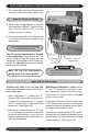
WLCA/WLHA HIGH WALL EVAPORATOR Installation Instructions REFRIGERANT PIPING Piping Do’s and Don’ts • Avoid piping on a rainy day. • Use refrigerant grade copper tubing. • Use a tubing bender and avoid unnecessary bending. • Cap ends of lines until ready for final connections. Once the unit is mounted and level the WLCA/WLHA piping connections can be made by removing the left end cap and bottom panel: Note: The left end cap must be removed prior to removing the bottom.
REFRIGERANT PIPING Any change in the diameter of the tubing must be made at the indoor connection. Line-set diameter is determined by the condenser service valve size.
WLCA/WLHA HIGH WALL EVAPORATOR Installation Instructions Refrigerant Processing ! Warning ! It is illegal to discharge refrigerant into the atmosphere. Use proper reclaiming methods and equipment when installing or servicing this unit. Finish all pipe connecting before proceeding to charging the system. Follow the instructions in the outdoor unit for line evacuation, opening service valves, and final charge adjustments. Operation charts and charge tables can be found in the EMI Condenser IOMs. 4.
WLCA/WLHA HIGH WALL EVAPORATOR Installation Instructions Refrigerant Processing Top discharge condeser shown 8. Charge to proper weight, charge based on your feet of interconnect (see below). Note: Charging should be done with a dial-a-charge or weighed in with a scale. Refer to Refrigerant Charge Table for specified line charge. nt igera Refr -22 R Important Notes: I.
WLCA/WLHA HIGH WALL EVAPORATOR Installation Instructions Reassembling the WLCA/WLHA cabinet When satisfied that the system is leak free reinstall the bottom and left end cap in the precise order shown below: Ensure seam is tight. 1. Replace the bottom panal. 2. Fasten the right end cap side first with the Philips-head screw. 5. Once end cap is properly seated tighten the screw as shown above. 6. Thighten bottom end cap screw. 3. Next replace and tighten the remaining screws across the bottom panel. 4.
Control User Interface instructions Quick Guide – User interface Buttons “MODE” button = select mode of operation, Cool, Heat, Auto changeover (ACO), Dry or Fan mode. “UP” arrow button = increase set “TIMER” button = enter or exit point temp., also = increment setSleep Timer mode. tings in Config., Time Set + Prog. modes. “TIME” button = enter or exit Set Time mode. “ON/OFF” button press once = unit on or off. “PROG” button = enter or exit “DOWN” arrow button = decrease set point temp.
Control User Interface instructions User interface Buttons FAN The “fan” button will select the fan speed, High, Low or Auto. High and low are constant fan speed settings and can be selected in all modes except Dry mode. In Dry mode, the fan will operate constantly at low speed. Auto fan mode is not available in Fan (only), Dry and Remote wall thermostat modes. ver mode. To enter the louver mode press and hold the Fan/Louver button for three seconds.
Sequence of Operation – Unit Mounted key pad mode Pressing the “ON/OFF” button once will switch the unit either on or off. In the Off mode, the LCD will display the time of day and day of the week. In the On mode the LCD display will also display the room temperature and the mode of operation Cool, Heat, Auto (Auto changeover), Dry or Fan mode. While in the On mode, the set point temperature will display momentarily with the push of any button except the ON/OFF button.
Sequence of Operation – Unit Mounted key pad mode or Down arrow buttons will allow selection of six different fixed louver positions or auto (oscillation) mode. The sequence is 01, 02, 03, 04, 05, 06 and Auto. Once the desired setting is selected, press the Fan/ Louver button momentarily or let idle for 10 seconds to exit the louver set mode. While the control is in the On mode, the louver will remain in the selected louver position.
Sequence of Operation – Unit Mounted key pad mode between room temperature and setpoint temperature is less than two degrees. At that time the electric heat will switch off and the heat pump (compressor) will take over the heating demand. The electric heater will not re-start until a three minute delay has elapsed. Once the room temperature is satisfied and the two-minute minimum run time has elapsed, the compressor will cycle off. The compressor will not re-start until a three minute delay has elapsed.
Sequence of Operation – Unit Mounted key pad mode any mode including the Off mode. To enter the Set Time mode, press the “TIME” button in for three seconds. Pressing the “PROG” (NEXT) button will advance to the next item. The order is (1) Day of week, (2) Hour and (3) Minute. Pressing the “MODE” (BACK) button will return to the previous item. The time of day and day of week can be changed using the up or down arrow buttons.
Sequence of Operation – Unit Mounted key pad mode Room Air Sampling Configuration Mode In the auto (cycling) fan mode Room Air Sampling will automatically cycle the fan on for a minimum of 60 seconds, with the control in the satisfied state, to periodically circulate room air. Room air stratification is therefore minimized due to the fan being off for long periods of time so that the microprocessor may accurately track room temperature. Room air sampling must be selected through the configuration mode.
Sequence of Operation – Unit Mounted key pad mode Sleep timer The sleep timer feature allows the user, with the push of a single button, to have the unit switch off using the preset timer. When the control is in the “On” mode, pressing the “TIMER” will enter or exit the Sleep Timer mode. When in Sleep Timer mode, the word “TIMER” will appear on the LCD display. The unit will continue to operate for thirty (30) minutes then switch off. Test mode To enter Test mode the control must first be in the Off mode.
Sequence of Operation – Wall mounted thermostat mode Heat Pump with Electric Heat: Select a thermostat that is compatible with a single stage cooling, two-stage heat, heat pump system. The thermostat should have “R”, “Y”, “O”, “W (or W2)” and “G” terminals. The thermostat may also have a “C” terminal. If the indoor unit is not equipped with electric heat then a single stage heat pump thermostat is adequate. Fan Operation The indoor unit utilizes a two-speed motor.
Sequence of Operation – Wall mounted thermostat mode place the system switch in Heat mode. Adjust the set-point temperature above the room temperature. The compressor and fan motors will start and heating will begin. Depending on the thermostat selected, electric heat will also energize when the deviation between room temperature and set point temperature is high enough to call for second stage heating.
Sequence of Operation – Wall mounted thermostat mode Note: While in Remote thermostat mode (see configuration), only the “FAN” and “TIME” buttons are activated and will beep when pressed. Memory Backup: In the event of a power failure the control will retain all of it’s settings including the mode of operation. When power is restored, after a three minute time delay, the control will return to the mode of operation that it was in prior to the power failure.
Optional Hand Held Controller programming Table #2 Temp Time Sunday Saturday Temp Time Temp Time Friday Thursday Temp Time Temp Time Tuesday Temp Time Monday Temp Time Morning Day Evening Night Wednesday Programming schedule Cool Heat Auto Cool Heat Auto Cool Heat Auto : : : : : : : : : : : : : : : : : : : : : : : : : : : : Cool Heat Auto To copy the settings from any day to the entire week: 1) Select the day to be copied.
Test Unit Performance Data sheet The Test Unit Performance Data sheet below is provided for use by a qualified service professional in the event that there is a problem with the unit. In order for our Technical Service Department to better serve you, please complete and have this information ready when calling. Make sure to include the Model Number, Serial Number, Date of installation. Call our Technical Support Department @ 1-800-228-9364.
MAINTENANCE and Troubleshooting procedure MAINTENANCE ! Warning a) To vacuum: Use a brush attachment and vacuum all visible dirt. ! Turn the power off to the unit before servicing or cleaning. Service should be performed by a qualified service agency and an annual system check is recommended. EMI units are designed and constructed for reliability and long life with minimal maintenance. To insure peak operating efficiency: 1.
MAINTENANCE and Troubleshooting procedure MAINTENANCE 4. Vacuum dust from the return air grille and coil surface when cleaning the filter. 5. The unit may be wiped with a damp cloth when needed. Note: Do not run the unit without the filter or the grille. Troubleshooting EMI Air handlers with Unit Mount Infrared Controls ! Warning ! All service should be performed by a qualified service technician.
Troubleshooting procedure Continued Figure 1B Figure 2 C Not used Power supply check Figure 2 A Figure 2 B When trouble shooting any EMI product, it is important to first check the rating plate for proper field voltage and breaker size. Secondly using a voltmeter check the incoming power supply to see that it agrees with the rating plate. The incoming power should not exceed the nameplate voltage.
Troubleshooting procedure Continued ! CAUTION ! While in test mode, all timers are eliminated. Avoid short cycling the compressor. After system checks are complete, the control must be returned to normal operation. DO NOT LEAVE THE SYSTEM IN TEST MODE! Low volt controls Cooling Only Units Cooling only units utilize low volt interconnecting wires between the indoor unit, outdoor units and thermostat.
Troubleshooting procedure Continued Optional Heat pump with Electric Heat Continued EMI heat pump systems utilize a reversing valve is that is energized in the cooling mode. The reversing-valve signal is provided through the orange (O) low volt wire of the air handler or thermostat. It should remain energized constantly as long as the indoor unit or thermostat remains in cooling mode.
Troubleshooting procedure Continued Frequently asked questions Q: The system has just been installed using an EMI indoor unit and a non-EMI condenser. There is no display and the unit will not operate. A: EMI air handlers are manufactured with a low volt transformer installed. When connecting an EMI evaporator to a nonEMI condenser, check to ensure that there is no 24v control transformer in the outdoor unit. Only one transformer is required.
Troubleshooting procedure Continued Frequently asked questions Continued to prevent freeze up from occurring. If freeze up does occur then check the following. • Is the equipment being operated in cooling mode when outdoor temperatures are below 60°F? If it is, then the condenser should be fitted with low ambient control so that the proper system pressures are maintained. • Check that the freeze sensor located in the lowest part of the coil. Generally this is where freeze up will begin.
WLCA/WLHA HIGH WALL EVAPORATOR Specifications and dimensions NOTE: Due to EMI’s ongoing development programs, design and specifications may change without notice.
WLCA/WLHA HIGH WALL EVAPORATOR Specifications WLCA/WLHA ELECTRICAL SPECIFICATIONS MODEL # FAN RLA VOLTS/HZ/PH HEATER AMPS K.W. HP TOTAL AMPS MIN VOLT M.C.A. HACR BRKR SMALL CABINET 09/12 09/12 115/60/1 0.64 0.02 – 115/60/1 0.64 0.02 0.75 – 208/230/60/1 0.34 0.02 – 208/230/60/1 0.34 0.02 3.00 6.50 – 0.64 104 0.8 15 7.14 104 8.9 15 0.34 197 0.4 15 13.04 13.38 197 16.7 20 MEDIUM CABINET 18/24 24 115/60/1 1.20 0.083 – 115/60/1 1.20 0.083 0.
WLCA/WLHA System Options NOTE: Due to EMI’s ongoing development programs, design and specifications may change without notice. WLCA/wlhA S2CA Side Discharge S1CA/S1HA Side Discharge Cooling Systems with Wall Units Condenser Wall Unit Btuh SEER SHR EER Ref. S1CA9 WLHA09 9,000 13.0 .79 11.8 R22 S1CA2 WLHA12 12,000 13.0 .74 12.9 R22 S1CA8 WLHA24 18,000 13.0 .78 13.0 R22 S1CA4 WLHA24 24,000 13.0 .70 12.5 R22 S1CA3 WLCA36 30,000 13.0 .72 12.
WLCA/WLHA System Options Continued NOTE: Due to EMI’s ongoing development programs, design and specifications may change without notice. WLCA T2CA, T3CA & T4CA Top Discharge System Options with T2CA TOP discharge Wall Unit(s) Condenser Btuh SEER SHR EER Ref. WLHA24 T2CA88 36,000 13 .79 12.1 R22 WLHA24 T2CA44 45,000 13 .73 11.8 R22 WLHA09+WLHA24 T2CA98 27,000 13 .80 11.8 R22 WLHA24 T2CA84 41,000 13 .76 11.8 R22 WLHA12+WLHA24 T2CA24 34,000 13 .72 11.
ALL PRODUCT LIMITED WARRANTY Enviromaster International LLC (EMI) warrants to the purchaser/owner that EMI products will be free from defects in material and workmanship under the normal use and maintenance for a period of twelve months for all components and sixty months on unit compressors from the date of original installation, or fifteen months for all components and sixty-three months on unit compressors from the date of manufacture, whichever comes first.
EMI’s High Efficiency Product Line Evaporators WLCA/WLHA High Wall Evaporator CACB Cassette Evaporator Condensers S1CA & S1HA Single Zone Side Discharge S2CA Dual Zone Side Discharge T2CA, T3CA & T4CA 2, 3 & 4 Zone Top Discharge Phone: 1-800-228-9364 Fax: 1-800-232-9364 5780 Success Drive, Rome, NY 13440