
Specifications


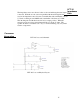

Do not attempt to disassemble these panels. The steel frame is preventing the
panel from collapsing on itself. Removal of the cap screws that hold the panel
together will surely cause damage to the diaphragm and may pinch hands and
fingers.
The mid-range panel design (shape and size) was chosen for good dispersion
and bandwidth.
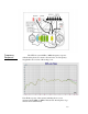
For a given speaker design, there is a direct trade off between maximum sound
pressure level, bandwidth and efficiency. In the LFT-16, the mid-range panel
is usable from 100 Hz to about 40 kHz. However, there are problems if you
use the panel over its full frequency range.
At the upper frequency limit, the panel will beam because the wavelength
becomes much shorter than the panel is wide. This is also the reason the
speaker sounds best within the vertical axis of the mid-range panel.
At the lower limit, the panels free air resonance is 120 Hz. This resonance is
damped almost 100% with cloth on the back magnet channel assembly.
Around 120 Hz at high sound pressure levels, the excursion limit of the
diaphragm will be exceeded and it will slap against the magnet channel. A
crossover point of 180 Hz is chosen to achieve a good maximum sound
pressure level and still have the mid-range panel play vocal fundamentals and
mid bass which is desirable for a good blend with the woofer. Since the lower
crossover frequency is 6 dB per octave, the panel still has substantial output
below 100 Hz.
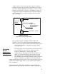
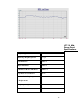
Near field response of the woofer 10Hz to 2Khz including the
crossover network. The near field measurement removes most of
the low frequency room modes.
Mid-Range
Panel
Design
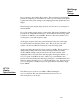
LFT-16
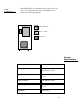
Woofer
Specifications
20