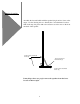
A complete technical description of the LFT-6 is included in this manual and begins on page 8. It is recommended that you become familiar with this information as a thorough understanding of the LFT principals will assist you in the proper set up of these loudspeakers. Installation of the LFT - 6 Position the box on its side and open the end of the shipping carton. Remove the padding from the bottom and slide the speaker from the box as shown below.
Speaker Assembly Assemble the feet and baffles with the speaker lying front face down on the carpet. Use the drawing below to identify the correct hardware locations. Grill cloths snap into place with velcro fasteners at each corner on the front and back of the speaker. 10-32 x 3/4 Socket Head Screw (6) 10-32 x 3/4 Socket Head Screw (2) 10-32 x 3/4 Socket Head Screw (4) It may help to have two people remove the speakers from the boxes because of their weight .
Speaker placement is critical for correct imaging, frequency balance, low frequency performance, and efficiency. Positioning the Speakers in the listening room Low frequency performance in particular can be determined by the shape of the room and the speaker's distance from the wall immediately behind them. Typically, the optimal distance between the LFTs and the rear wall is 2 to 5 feet in an average room.
Overall Balance and Toe-In The overall frequency balance of the LFT-6 is somewhat affected by the degree to which the speakers are toed in toward the central listening position. The on-axis frequency response of the LFTs is essentially flat, and it is often best to position the speakers so that the main listening position is about on axis with each speaker.
The high frequency performance of the LFTs can be tailored with the tweeter lever control. A jumper is mounted under the crossover cover. There are three tweeter level positions. If the jumper is disconnected, the treble energy is rolled off slightly and this is the lowest setting. When the jumper is connected to the third terminal up from the bottom of the right hand row of six terminal points, the tweeter output at its middle position.
Bi-Wiring and BiAmping The LFT-6is configured to allow bi-wiring or bi-amping with a minimum of trouble. The two pairs of inputs on the crossover are connected together internally, hot to hot and ground to ground. During normal use, speaker cables can be connected to either the top or bottom pair of inputs. Cutting the Terminal Jumpers For bi-wiring or bi-amping, the internal jumpers connecting the upper and lower input terminals must be severed.
Bi-amping requires and additional stereo amplifier or pair of mono amps. You will also need some means of insuring that only the desired portion of the frequency range reaches each amplifier. The simplest way to accomplish this is with an external electronic crossover; however, this can also be done by hard-wiring low-pass and high-pass filters into the inputs of the bass/mid and treble amplifiers, respectively.
Technical Description The Eminent Technology Linear Field Transducer is a full-range, push-pull, dynamic planar loudspeaker. In a sense, it is the magnetic equivalent of a push-pull electrostatic loudspeaker, differing in that it requires no step-up transformer or bias voltage, and that the audio signal is applied directly to its diaphragm.
antecedents: the push-pull electrostatic loudspeaker (ESL); the traditional, single-ended planar magnetic loudspeaker, and the ribbon loudspeaker.
Electrostatic Loudspeakers The electrostatic starts with a very thin (half mil or less) diaphragm made of mylar or a similar material, to which a light coating of mildly conductive substance such as graphite has been applied. This diaphragm is suspended on a rigid frame and sandwiched between two stationary conductive grids (usually perforated metal plates) called stators.
The traditional planar magnetic also starts with a thin mylar diaphragm, one side of which is coated with adhesive and fitted with an aluminum wire voice grid, (analogous to the voice coil of a conventional cone driver). The diaphragm is held taut in a metal frame. On the front of this frame is a large sheet of perforated metal, to which rows of vertically aligned strip magnets have been fastened.
Ribbon Loudspeakers The third and final antecedent to consider is the ribbon: a distinctly different sort of transducer, but one that is similar (in principle, at least) to the single-ended planar magnetic. The ribbon’s primary distinction is that its “diaphragm” and “voice element” are one and the same. A ribbon driver is based on a long, narrow strip of conductive material; in practice, thus far, all true ribbons have used a strip of very thin corrugated aluminum for this purpose.
Not surprisingly, each of the approaches described above has its own unique set of pros and cons. The electrostatic, because its diaphragm is so thin and light, offers exceptionally good transient response and reproduction of subtle, low-level musical detail. And, because it is a true push-pull device (i.e., its diaphragm is, by design, driven from both the front and the rear), the ESL operates in a linear fashion.
Also, when a ribbon is operated at frequencies approaching the element’s own resonant frequency (which is naturally quite low, due to its high compliance), the ribbon element stretches and “bows” to a point where it is no longer within the magnetic gap.
Eminent Technology’s Linear Field Transducer, introduced as the LFT, represents a new approach to the design and construction of a high-quality loudspeaker*. It builds on the strengths of the above designs while eliminating many of their drawbacks. The Linear Field Transducer The construction of the LFT -6 begins by laminating a very thin sheet of aluminum foil to a half-mil-thick sheet of Mylar.
By applying such new techniques to planar loudspeaker construction, Eminent Technology has been able to eliminate many of the flaws inherent in earlier designs. The use of a welded channel-and-crossbar frame dispenses with the need for perforated sheet metal (an “off-the-shelf” material presumably used for reasons of economy and ease of manufacture.) thus greatly improving dispersion, especially at high frequencies.
Each LFT has five individual driver panels. The outside portion on each panel is divided into separately driven bass and (line-source) midrange areas, with the former operating from 400 Hz down, and the latter operating from 400 Hz up to 10 kHz. The tweeters operate as a line source from 10 kHz up to and beyond 20 kHz. The midrange and tweeter sections are distinguishable by their thinner magnet structures.
surface area of the panels and the resulting good heat dissipation (a function also of the material choice for the voice grid), the LFT-6 can handle tremendous amounts of power before any risk of damage.
Power Requirements: 100 watts minimum Sensitivity 83 dB (pink noise, 20-20 kHz) at 1 watt/1 meter (2.83 V) Frequency Response 38 Hz-20 kHz ±4 dB (typical room, close-mic measurement) -10 dB at 35 kHz Phase Accuracy ± 20° 100 Hz-31 kHz High Frequency Level Flat, -6 dB, -12 dB at 20 kHz smooth rolloff Impedance 6 Ohm rating Maximum SPL 105 dB at 1 meter Magnet type Ceramic 8 Diaphragm Area 420 in2 (front) Harmonic Distortion Less than .
David Collie and Bruce Thigpen Designers 20
Technical information 21
Technical information 22
Technical information 23
Technical information 24
Eminent Technology Inc. warrants the LFT Loudspeaker to be free from defects in materials and workmanship for a period of 30 days from the date of purchase. Within that period, any failure of the LFT will be corrected without charge for parts, labor, or transportation from the factory.