EMINENT TECHNOLOGY INCORPORATED LFT-8b HYBRID LINEAR FIELD TRANSDUCER LOUDSPEAKER ® REFERENCE MANUAL Revised: 10/30/07 Eminent Technology, Inc. 225 East Palmer Street Tallahassee, Florida 32301 Phone: (850) 575-5655 FAX: (850) 224-5999 Email: info@eminent-tech.com Website: www.eminent-tech.
Extremely strong magnetic fields are present at and around this loudspeaker. Devices that are adversely affected by high levels of magnetic flux, such as television sets and pacemakers, should be kept at least three feet away from each speaker. Also, keep in mind when any ferrous objects are brought close to the speakers. Hold steel tools securely when setting up and adjusting the LFT8b, to prevent a hex key or screwdriver from slipping from your hand and damaging the Mylar diaphragm.
TABLE OF CONTENTS Installation of the LFT-8b........................................................... 5 Unpacking the Speakers............................................................. 5 Speaker Assembly...................................................................... 6 Positioning the Speakers in the Listening Room........................7 Imaging....................................................................................... 7 The Tweeter Level Control.....................................
Woofer Enclosure....................................................................... 30 Warranty..................................................................................... 31 Appendix A – Hex Cam Spacer Installation............................ 33 Appendix B – Tweeter Diaphragm Replacement....................
Installation of the LFT-8b A complete technical description of the LFT-8b is included in this manual and begins on page 10. It is recommended that you become familiar with this information because an understanding of the LFT principals will assist you in the proper set up of these loudspeakers. The LFT-8b is shipped in 3 boxes. The larger square box contains the two woofer cabinets. The 2 long rectangular boxes contain the panels and grills.
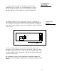
Speaker Assembly Assemble the panel to each woofer cabinet as shown below. Fasten the feet to the bottom of the woofer cabinet. Use the drawing below to identify the correct hardware locations. Grill cloths snap into place with Velcro fasteners at each corner on the front and back of the speaker. Bolt the woofer box to the panel as illustrated below. Laying the speaker on its side may be helpful in assembly.
Speaker placement is critical for correct imaging, frequency balance, low frequency performance, and efficiency. The LFT-8b speakers are a mirror image pair and should be set up with the tweeter panels to the inside. Positioning the Speakers in the Listening Room Low frequency performance in particular can be determined by the shape of the room and the speaker's distance from the wall immediately behind them.
The Tweeter Level Control The high frequency performance of the LFT’s can be tailored with the tweeter level control. The high frequency performance of the LFT-8b is adjusted with the tweeter level control. There are three tweeter level positions: High, Mid and Low. These levels adjust the tweeter output in approximately 3 dB increments.
The LFT-8b is configured to allow bi-wiring or bi-amping with a minimum of trouble. Bi-Wiring and Bi-Amping Bi-wiring simply means connecting a single stereo amplifier (or two mono amps) to a pair of speakers by using two pairs of speaker cables. Connect the hot and ground conductors of a pair of cables to the same output terminals on one channel of the amplifier; the other ends are connected to the separate woofer and mid/tweeter inputs of the LFT-8b (All speaker cables should be the same length).
Technical Description The Eminent Technology Linear Field Transducer is a full-range, push-pull, dynamic planar loudspeaker. In a sense, it is the magnetic equivalent of a push-pull electrostatic loudspeaker, differing in that it requires no step-up transformer or bias voltage, and that the audio signal is applied directly to its diaphragm.
The electrostatic starts with a very thin (half mil or less) diaphragm made of Mylar or a similar material, to which a light coating of mildly conductive substance such as graphite has been applied. This diaphragm is suspended on a rigid frame and sandwiched between two stationary conductive grids (usually perforated metal plates) called stators.
Planar Magnetic Loudspeakers The traditional planar magnetic also starts with a thin Mylar diaphragm, one side of which is coated with adhesive and fitted with an aluminum wire voice grid, (analogous to the voice coil of a conventional cone driver). The diaphragm is held taut in a metal frame. On the front of this frame is a large sheet of perforated metal, to which rows of vertically aligned strip magnets have been fastened.
The third and final antecedent to consider is the ribbon: a distinctly different sort of transducer, but one that is similar (in principle, at least) to the single-ended planar magnetic. The ribbon’s primary distinction is that its “diaphragm” and “voice element” are one and the same. Ribbon Loudspeakers A ribbon driver is based on a long, narrow strip of conductive material; in practice, thus far, all true ribbons have used a strip of very thin corrugated aluminum for this purpose.
Evaluating Not surprisingly, each of the approaches described above has its own unique set of pros and cons. The electrostatic, because its diaphragm is Earlier Approaches so thin and light, offers exceptionally good transient response and Electrostatics reproduction of subtle, low-level musical detail. And, because it is a true push-pull device (i.e., its diaphragm is, by design, driven from both the front and the rear), the ESL operates in a linear fashion.
Also, when a ribbon is operated at frequencies approaching the element’s own resonant frequency (which is naturally quite low, due to its high compliance), the ribbon element stretches and “bows” to a point where it is no longer within the magnetic gap.
The Linear Field Transducer Diaphragm Construction The Magnet/Frame Structure Eminent Technology’s Linear Field Transducer, introduced as the LFT, represents a new approach to the design and construction of a high-quality loudspeaker*. It builds on the strengths of the above designs while eliminating many of their drawbacks. The construction of the LFT –8b begins by laminating a very thin sheet of aluminum foil to a half-mil-thick sheet of Mylar.
By applying such new techniques to planar loudspeaker construction, Eminent Technology has been able to eliminate many of the flaws inherent in earlier designs. The use of a welded channel-and-crossbar frame dispenses with the need for perforated sheet metal (an “off-the-shelf” material presumably used for reasons of economy and ease of manufacture.) thus greatly improving dispersion, especially at high frequencies.
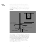
Panel Frequencies Each LFT-8b has two individual driver panels and a cone type woofer. The placement of the individual drivers is shown in the following diagram.
Technical information General Specifications: Power Requirements 75 Watts minimum Sensitivity 84 dB (pink noise, 20 - 20kH) at 1 watt/1 meter (2.83 V) Frequency Response 25 Hz-50 kHz ±4 dB (typical room) Phase Accuracy ± 20˚ 100 Hz-31 kHz High Frequency Level Flat, - 6dB, -12dB at 20kHz smooth roll off Impedance 8 Ohm rating Maximum SPL 105 dB at 1 meter Dimensions 13” wide by 60” high by 1” thick Shipping Weight 90.5 lbs.
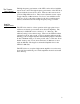
Technical information LFT-8b Impedance Curves The LFT-8b impedance is shown below. The impedance generally averages much higher than 8 ohms. This means that the speaker does not require a high current amplifier. Because of the lower than average efficiency you will still need an amplifier with a fairly high power rating (75 watts per channel or more). If an amplifier clips into the speaker it will probably be due to a voltage limitation.
Technical information LFT-8b Impedance Data The impedance curves shown below are for the woofer and mid-range/tweeter inputs measured individually. The woofer curve shows an impedance minimum at 75Hz (10 ohms) and a steady rise above 100 Hz due to series inductance. The mid-range and tweeter section impedance curves trends down through the frequency range.
Technical Information Crossover Information LFT-8b Crossover Schematic LFT-8b Crossover Physical Layout 22
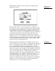
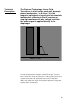
Technical Information Square Wave Performance The square wave performance of the LFT-8b is shown below at different frequencies. Measurements were made in a normal listening room, and the microphone position was optimized for each frequency. In order for a loudspeaker to reproduce a square wave, it must have good frequency response, phase response, impulse response and transient response.
Technical Information Frequency Response 1/3 Octave, One Watt, One Meter 24
Technical Information LFT-8b Panel Specifications Magnet Type Ceramic 8 Mid-range Diaphragm area 126 sq in Foil Thickness .00033 Mylar Thickness .0005 Laminate Adhesive Thickness .00015 Gap Between Conductors .03 Peak-to-Peak Diaphragm .180 Displacement Tweeter Diaphragm area 10 sq in Tweeter Peak to Peak Displacement .
Technical information Mid-Range Panel Design Do not attempt to disassemble these panels. The steel frame is preventing the panel from collapsing on itself. Removal of the cap screws that hold the panel together will surely cause damage to the diaphragm and may pinch hands and fingers. The mid-range panel design (shape and size) was chosen for good dispersion and bandwidth. For a given speaker design, there is a direct trade off between maximum sound pressure level, bandwidth and efficiency.
Technical Information LFT-8b Woofer Specifications Box Volume 23 Liters 1403 in3 .812 ft3 Speaker Diameter 8 inch Magnet weight 33 oz. Impedance 8 Ohms DC Resistance 6.79 Ohms Inductance 3.89 mH Free Air Resonance 19.65 Hz ±15% CMS 0.6570 E-03 M/N MMS 99.8Grams VAS 37.62 Liters QMS 6.02 QES .361 QTS .34 B1 15.32 T-M ZM 121.
Technical Information Additional Woofer Specifications FC 31.73 Hz RE 6.79 Ohms F1 23.3 F2 46.2 QM Fc r o F2 − F1 3.610 QE Qm ro − 1 0.623 QT QM QE QM + QE 0.
Technical Information Woofer Design The design goal for the woofer is good transient response, low Q, low cutoff frequency and minimal coloration near the crossover region. For the cabinet size dictated by design, no available off the shelf woofers met our design requirements. Most off the shelf woofers are designed to operate over a much wider bandwidth than is desirable for the LFT-8b. In a hybrid system of this type, it is desirable to have as low a crossover frequency as possible for the woofer.
Technical Information Woofer Enclosure The design goal for the woofer enclosure is: (1) To be as resonance free as possible (rigid) to prevent low frequency and mid-range colorations. (2) To provide sufficient internal volume to give the desired frequency response. (3) To visually appear smaller than it is when attached to the rest of the speaker.
Eminent Technology Inc. warrants the LFT Loudspeaker to be free from defects in materials and workmanship for a period of 30 days from the date of purchase. Within that period, any failure of the LFT will be corrected without charge for parts, labor, or transportation from the factory.
EMINENT TECHNOLOGY, INC.
Appendix A HEX CAM SPACER INSTALLATION AND ADJUSTMENT FOR THE LFT-8b Tools needed: 5/32 Allen Wrench 7/16 Open End Wrench (aluminum recommended) INSTALLATION 1.) Remove machine screws (4) and spacers (8) at the 4 centrally located crossbars along outside edge of diaphragm frame (opposite tweeter) taking care not to damage diaphragm. Loosen machine screws at points B in Figure 1 three turns. 2.) Install hex cam spacers at locations shown in Figure 1 making sure cam portion fits into hole in frame.
Appendix B TWEETER DIAPHRAGM REPLACEMENT FOR THE LFT-8b Revised 10/26/2007 Remove the tweeter driver completely from the speaker frame. Disconnect the black tweeter wire spade lug from the barrier terminal block and detach the white tweeter wire from the mid-range terminal board using a soldering iron. Remove the eight machine screws, nuts and spacers. Keep track of each spacer location so that it can be returned to that same position upon re-assembly.
Assembling and Installing The Tweeter Driver Re-assembly of the tweeter driver should be done in the exact reverse order as it was disassembled. Re-install the tweeter driver into the speaker frame placing the spacers in their original locations. Run the black and white tweeter wires next to the two lower cross bar spacers, of the midrange assembly, and tie wrap both wires to each spacer. Attach the spade lug to the proper tweeter setting on the barrier terminal block to the.