Temperature Controller ESM-1510 DIN Rail Mounting ESM-1510 DIN Rail Mounting Type Digital, ON / OFF Temperature Controller - 3 Digits display - NTC Input or, PTC Input or, J type thermocouple Input or, K type thermocouple Input or, 2-Wire PT 100 Input or, 2-Wire PT 1000 Input (It must be determined in order) - ON/OFF temperature control - Selectable heating or cooling function - Selection of operation with hysteresis - Adjustable temperature offset - Set value low limit and set value high limit boundaries
ABOUT INSTRUCTION MANUAL Instruction manual of ESM-1510 Temperature Controller consists of two main sections. Explanation of these sections are below. Also, there are other sections which include order information and technical specifications of the device. All titles and page numbers in instruction manual are in “CONTENTS” section. User can reach to any title with section number.
Contents 1.PREFACE............................................................................................................................................ Page 1.1 GENERAL SPECIFICATIONS 1.2 ORDERING INFORMATION 1.3 WARRANTY 1.4 MAINTENANCE 5 2.INSTALLATION.................................................................................................................................... Page 2.1 GENERAL DESCRIPTION 2.2 FRONT VIEW AND DIMENSIONS OF ESM-1510 TEMPERATURE CONTROLLER 2.
EU DECLARATION OF CONFORMITY Manufacturer’s Name : EMKO ELEKTRONIK A.S. Manufacturer’s Address : DOSAB, Karanfil Sk.
1.Preface ESM-1510 series temperature controllers are designed for measuring and controlling temperature. They can be used in many applications with their On / Off control form, heating and cooling control form and easy-use properties. Some application fields which they are used are below: Application Fields Glass Plastic Petro-Chemistry Textile Automative Machine production industries Applications Heating Baking Ovens Incubators Storages Air Conditioning 1.
1.2 Ordering Information A BC D E / FG HI / U V W Z / 00 00 / 2 0 0 ESM-1510 0 A Supply Voltage 2 3 4 5 8 9 BC 05 10 11 09 12 15 14 13 18 19 24 V W ( - 15%, + 10% ) 50/60 Hz 24 V V ( ± 15% ) 50/60 Hz 115 V V ( ± 15% ) 50/60 Hz 230 V V ( ± 15% ) 50/60 Hz 10...30 V Z Customer Input Type J, Fe CuNi IEC584.1(ITS90) K, NiCr Ni IEC584.
2.Installation c Before beginning installation of this product, please read the instruction manual and warnings below carefully. In package , - One piece unit - One piece rail lock apparatus - One piece instruction manual A visual inspection of this product for possible damage occured during shipment is recommended before installation. It is your responsibility to ensure that qualified mechanical and electrical technicians install this product.
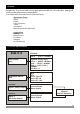
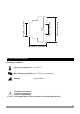
2.1 General Description Rail Lock Apparatus 2.2 Front View and Dimensions of ESM-1510 Temperature Controller 7 8 6 ESM-1510 °C P SV Temperature Controller SET 1 2 3 4 86 mm / 3.38 inch 9 5 35 mm / 1.
86 mm / 3.38 inch 35 mm / 1.38 inch 46.5 mm / 1.83 inch 59 mm / 2.32 inch 2.3 Environmental Ratings Operating Conditions Operating Temperature : 0 to 50 °C Max. Operating Humidity : 90 % Rh (non-condensing) Altitude c : Up to 2000 m.
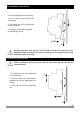
2.4 Installation onto the Rail The unit is designed for rail mounting. 1- Put into the unit upper side of the rail properly. 2- Pull down the rail lock apparatus via a screw driver. 1 3.-Push the unit from the underside for mounting to the rail. 3 2 c During installation onto the rail, care should be taken to avoid injury from mechanical part of the system. These precautions for the safety of the person who does the rai mounting. 2.5 Removing from the Rail c 2.
3.Electrical Wiring c c c c You must ensure that the device is correctly configured for your application. Incorrect configuration could result in damage to the process being controlled, and/or personal injury. It is your responsibility, as the installer, to ensure that the configuration is correct. Device parameters has factory default values. These parameters must be set according to the system’s needs. Only qualified personnel and technicians should work on this equipment.
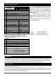
3.2 Electrical Wiring Diagram c Electrical wiring of the device must be the same as ‘Electrical Wiring Diagram’ below to prevent damage to the process being controlled and personnel injury. Temperature Sensor Input (TC, NTC, PTC, PT-100 or PT-1000) 7 6 TC NTC, PTC, PT-100, PT1000 ESM-1510 °C P SV Temperature Controller SET OUTPUT 5A@250V V C 1 2 L(+) N(-) 3 NC 4 NO 5 (-) (+) For SSr Output Supply Voltage Input 230 V V ( ± %15 ) 50/60 Hz - 1.
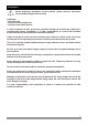
3.3 View of the Device Label Device Label for J Type ( 0 ; 800 ) scaled, Thermocouple input , 230V V Supply Voltage Input and Relay Output c aY CAT II P/N : ESM-1510 5.05.0.1/00.00/2.0.0.0 P/N : ESM-1510 5.05.0.1/00.00/2.0.0.0 L N 1 2 J Type TC ( 0 to 800°C) Scale OUTPUT 5A@250V V 230 VV ± 15% 50/60Hz - 1.5VA C 3 NC 4 NO 5 6 7 Device Label for PT-100 Type ( -50 ; 400 ) scaled, Thermoresistance input , 230V V Supply Voltage Input and Relay Output c aY P/N : ESM-1510 5.11.0.1/00.00/2.0.0.
3.4 Supply Voltage Input Connection of the Device Connection of Supply Voltage Input Y aN L 1 Note-1 Note-2 External Fuse (1 A T) 2 Power Supply Switch c Supply Voltage 230 V V (± 15%) 50/60 Hz or 115 V V (± 15%) 50/60 Hz or 24 V V (± 15%) 50/60 Hz or 24 V W (- 15%, + 10%) 50/60 Hz or 10...30 V Z Note-1: “L” is (+), “N” is (-) for 10...30V Z and 24V Z Supply Voltage Note-2: External Fuse is recommended c c Make sure that the power supply voltage is same indicated on the instrument.
3.5 Temperature Sensor Input Connection 3.5.1 TC (Thermocouple) Connection TC 7 i i Connect the wires with the polarity as shown in the figure left. 6 Always use compensation wire corresponding to the thermocouple used. If present, the shield must be connected to a proper ground. Input resistance is greater than 10M W. 3.5.2 PTC and NTC Connection PTC NTC RED WHITE 7 i i 6 7 6 Input resistance is greater than 10M W.
3.5.3 PT-100 and PT-1000 Connection PT-1000 PT-100 7 i 7 6 6 Input resistance is greater than 10M W. 3.6 Galvanic Isolation Test Values of ESM-1510 Temperature Controller 2000 V V ( For ESM-1510.5...... ) 500 V V ( For ESM-1510.3......
3.7 Output Connections 3.7.1 Relay Output Connection L N Device NC C NO c c 4 Max 5A V T Fuse 3 5 Load Fuses must be selected according to the application. 3.7.2 SSR Driver Output Connection Device 4 L N Last Control Element (SSR) 5 Max. 15 V Z Max. 28mA c Fuse Load c Fuses must be selected according to the application.
4. Front Panel Definition and Accessing to the Menus Displays Temperature Value,Temperature Set Value and Parameters ESM-1510 Led indication of SET value changing mode °C Led indication of Output is active (If blinks, Compressor protection time is active) P SV Temperature Controller Note-1 It is used to increase the value and access to the parameter in programming mode.
4.2 Changing and Saving Set Value SET Value Screen Operation Screen °C P SV °C When SET button is pressed, SV LED lights on and SET value is shown on the displays. SET °C P SV SET Change the SET value with increment and decrement buttons. SET Value Screen Operation Screen °C P SV SET Press SET button for saving the SET value °C P SV SET SV LED lights off and main operation screen is shown.
4.3 Program Parameters Hysteresis Parameter for Output ( Default = 1 ) 1 to 100 °C for TC Type Devices, 1 to 100 °C for PT-100 (-50°C , 400°C) and PT-1000 (-50°C , 400°C), 0.1 to 10.0 °C for PT-100 (-19.9°C, 99.9°C) and PT-1000 (-19.9°C, 99.9°C), 1 to 20 °C for PTC (-50°C, 150°C) and NTC (-50°C, 100°C), 0.1 to 10.0 °C for PTC (-19.9°C, 99.9°C) and NTC (-19.9°C, 99.9°C) Minimum Set Value Parameter ( Default =Minimum value of device scale ) Set value can not be lower than this value.
4.
4.
Probe Defect Parameter Compressor is active during this time period in case of probe defect °C P °C P SV SET SV SET i SV SET Hysteresis Parameter °C °C P °C P SV SET Programming Mode Accessing Password Compressor is inactive during this time period in case of probe defect P SV SET If no operation is performed in Programming mode for 20 seconds, device turns to operation screen automatically 23
2-If Operating Type Parameter Value = 0 (Heating), Programlama Modu Giriþ Ekraný Ana Çalýþma Ekraný °C P °C P SV 5 sn SET SET SET SET/ONAY Butonu ile þifrenizi onaylayýnýz.
4.6 Entering To The Programming Mode, Changing and Saving Parameters Programming Mode Entering Screen Operation Screen °C P °C P SV SET 5 secs Press increment button for accessing to the password entering screen. SV SET When SET button is pressed for 5 seconds, “P” led starts to blink. If programming mode entering password is different from 0, programming mode entering screen will be observed.
Hysteresis Parameter Value Hysteresis Parameter °C °C P P SV Press Set button for saving the parameter value SET Press Set button for accessing to the next parameter Minimum Set Value Parameter P SV SV SET Minimum Set Value Parameter is accessed by pressing °C increment button. If set button is pressed, next parameter is shown.
5. Failure Messages in ESM-1510 Temperature Controller ESM-1510 Probe defect in analogue inputs. Sensor connection is wrong or there is no sensor connection. °C P SV Temperature Controller SET 6. Specifications Device Type Housing&Mounting Protection Class Weight Environmental Ratings : Temperature Controller : 86mm x 35mm x 59mm plastic housing for Rail Mounting. : IP20. : Approximately 0.14 Kg. : Standard, indoor at an altitude of less than 2000 meters with none condensing humidity.
7. Other Informations Manufacturer Information: Emko Elektronik Sanayi ve Ticaret A.Þ. Demirtaþ Organize Sanayi Bölgesi Karanfil Sk. No:6 16369 BURSA/TURKEY Phone : +90 224 261 1900 Fax : +90 224 261 1912 Repair and Maintenance Service Information: Emko Elektronik Sanayi ve Ticaret A.Þ. Demirtaþ Organize Sanayi Bölgesi Karanfil Sk. No:6 16369 BURSA/TURKEY Phone : +90 224 261 1900 Fax : +90 224 261 1912 Thank you very much for your preference to use Emko Elektronik Your Technology Partner Products. www.