
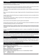
Instructions

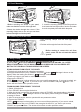
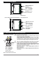


4. Electrical Wiring Diagram
4.1 Supply Voltage Input Connection of the Device
Note-1 : External fuse is recommended.
Make sure that the power supply voltage is the same
indicated on the instrument.
Switch on the power supply only after that all the electrical
connections have been completed.
Supply voltage range must be determined in order. While
installing the unit, supply voltage range must be controlled
and appropriate supply voltage must be applied to the unit.
c
There is no power supply switch on the device. So a power
supply switch must be added to the supply voltage input.
Power switch must be two poled for seperating phase and
neutral, On/Off condition of power supply switch is very
important in electrical connection.
External fuse that on Vpower supply inputs must be on
phase connection.
External fuse that on Zpower supply inputs must be on (+)
connection.
c
6
Power Supply Connection
c
a
EXTERNAL
FUSE
(1A T)
Note-1
Supply
Switch
Supply Voltage
4
5
L
N
230V ( %15) 50/60Hz ,
115V ( %15) 50/60Hz,
24V ( %15) 50/60Hz ,
24V ( %15) 50/60Hz ,
Z
V ±
V ±
V ±
W ±
10..30 V - 1.5 W
Must be determined in order.
Relay or SSR Output
21 4 5 6 7
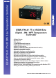
P/N : ESM-3710-N
L
N
a
Supply Voltage Input
Temperature Sensor
TC,NTC,PTC,PT-100
or PT-1000
Input
230V ( %15) 50/60Hz
115V ( %15) 50/60Hz
24V ( %15) 50/60Hz
Z
V ±
V ±
V ±
10...30 V
Must be determined in order.
3
(+)
(-)
For SSR Output
(+)(-)
Relay Output
30(15)A@240 V V
21 5 6 7 8
P/N : ESM-3710-N
L
N
a
Supply Voltage Input
Temperature Sensor
NTC
Input
230V ( %15) 50/60Hz
115V ( %15) 50/60Hz
24V ( %15) 50/60Hz
Z
V ±
V ±
V ±
10...30 V
Must be determined in order.
3 4
Electrical Wiring Diagram for 30(15)A @ 240 V V Relay Output Devices: