
Instructions
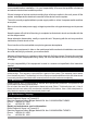


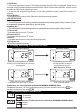
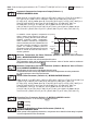

5.Front Panel Definition and Accessing to the Menus
BUTTON DEFINITIONS
1. Increment Button :
** It is used to increase the value in the Set screen and Programming mode.
2. Decrement, Silencing Buzzer and Downloading to Prokey Button :
** It is used to decrease the value in the Set screen and Programming mode.
** It is used to silence the buzzer.
** If Prc =0, it is used to download from device to prokey.
O
F
O
C
P
S
5 6 7 7
9
10
1
2
3
4
8
7
6
ü
ESM3710-N
SET
P
3
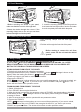
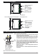
4.2 Device Label and Connection Diagram
230VV CONNECTION DIAGRAM
PROKEY
RS-485
or
6
7
a
16(8)A
@250VV1HP
L
N
2
4
5
1
NTC
L
N
16A Fuse
3
NCNO
C
OUTPUT
INPUT SCALE
(-50 ,100 ; -58 ,212 ) °C °C °F °F
NTC
16(8)A @
250VV1HP
230 VV ± 15%
50/60Hz - 1.5VA
P/N : ESM-3710-N - 5.18.0.1/00.00/2.3.0.0
PROKEY
RS-485
or
7
OUTPUT
NO NCC
LINE
LOAD
LOAD
Supply Voltage InputConnection for 30(15)A @ 240 V V Relay Output Devices:
c
a
EXTERNAL
FUSE
(1A T)
Note-1
Supply
Switch
Supply Voltage
5
6
L
N
230V ( %15) 50/60Hz ,
115V ( %15) 50/60Hz,
24V ( %15) 50/60Hz ,
24V ( %15) 50/60Hz ,
Z
V ±
V ±
V ±
W ±
10..30 V - 1.5 W
Must be determined in order.
(+)(-)
30(15)A @ 240 V V Connection Diagram for Relay Output Devices:
INPUT SCALE
(-50 ,100 ; -58 ,212 ) °C °C °F °F
NTC
230 VV ± 15%
50/60Hz - 1.5VA
P/N:ESM-3710-N-5.18.0.3/00.00/2.3.0.0
PROKEY
RS-485
or
7 8
30(15)A @ 240VV
OUTPUT
PROKEY
RS-485
or
7
8
a
30(15)A@240VV
L
N
2
54
6
1
NTC
L
N
30A Fuse
3
OUTPUT
LOAD