
Instructions
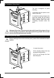
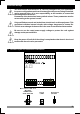
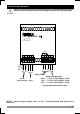

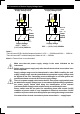
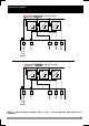
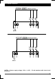
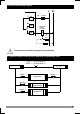
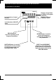
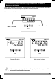
Table Of Contents

15
3.4 Connection of Device Supply Voltage Input
Note-1 :
There is internal 33 R W fusible 115V V 50/60 Hz and 230VV 50/60 Hz
There is internal 4R7 W fusible 24V V 50/60Hz
flameproof resistor in
flameproof resistor in
Supply Voltage
115VV, 230 V V
(-%15;+%10) 50/60 Hz
14
N L
15
Y
Power
Supply
Switch
c
a
External
Fuse
(1 A V T)
Note-2
24V V (-%15;+%10) 50/60Hz
14
L
15
Y
c
a
External
Fuse
(1 A V T)
N
Power
Supply
Switch
Note-2
Note-1
Note-1
Fuse
Fuse
Note-2 : External fuse is recommended
Connection of Universal
Supply Voltage Input
Connection of Universal
Supply Voltage Input
Supply Voltage
Supply voltage range must be determined in order. While installing the unit,
supply voltage range must be controlled and appropriate supply voltage must
be applied to the unit. Controlling prevents damages in unit and system and
possible accidents as a result of incorrect supply voltage.
There is no power supply switch on the device. So a power supply switch must
be added to the supply voltage input. In accordance with the safety regulations,
the power supply switch shall bring the identification of the relevant
instrument.Power supply switch shall be easily accessible by the user.
Power switch must be two poled for seperating phase and neutral. On/Off
condition of power switch is very important in electrical connection. On/Off
condition of power switch must be signed for preventing the wrong connection.
Make sure that the power supply voltage is the same indicated on the
instrument.
Switch on the power supply only after that all the electrical connections have
been completed.
c
c
If an external fuse is used, it must be on phase connection in Vsupply input.