Air Conditioners Serie: XEVO-XX17W43 WALL GB INSTALLATION MANUAL AND USING INSTRUCTIONS FOR INTERNAL UNIT
GB Thanks you for the trust you have shown by purchasing this produtc. Carefully read this manual which contains the specifications and all the information useful for the correct functioning. The information contained in this publication may be subject to changes at any time and without any notice whatsoever for technical and/or commercial reasons as they arise. Warning! Keep these manuals in a dry place avoiding in this way to spoil them.
GB INDICE 1. INTRODUCTION TO THE PRODUCT.... 4 8. AIR CONDITIONER SET-UP............. 23 1.1 Introduction to the conditioning 8.1 Air conditioner start-up 1.2 Refrigeration circuit 8.2 Fan functioning 1.3 Air conditioner composition 8.3 Cooling functioning 1.4 Internal unit 8.4 Heating functioning 1.5 Internal unit display 8.5 Dehumidification functioning “Dry” 1.6 Accessories supplied with the internal unit 8.6 Automatic functioning 1.7 External unit 8.
GB 1. INTRODUCTION TO THE PRODUCT 1.1 Introduction to conditioning Air conditioner function is to create perfect temperature and humidity conditions in the rooms they are installed, optimal conditions are able to satisfy human exigencies, in one word “comfort”. Working principle is to use refrigerant gas status changes (liquid/vapour) which is included in the internal refrigeration circuit, to subtract heat from one room and move it to another one. 1.
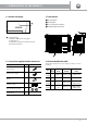
GB 1. INTRODUCTION TO THE PRODUCT 1.5 Internal unit display 1.7 External unit 1 Air outlet grille Air inlet grille Door to electrical connection Refrigerant pipe connections 2 Display temperature: - In AUTO mode, COOL and HEAT are displayed The temperature set; - The temperature is displayed in the FAN and DRY modes Of the internal environment. 3 Q.
Spegnere 2. WARNINGS 2.1 Attention and dangers MEANING OF SYMBOLS Before using the air conditioner please read carefully the instructions manual. Producer decline every responsibility for any damage caused by the non-observing of the following warnings. When this manual has been read, please make sure that further unit users will read it as well. User has to keep this manual close to hand and has to give it to those who repair and move the unit.
2. WARNINGS GB Before any maintenance remove the power supply from the air conditioner. Use the air conditioner only to condition the room. Do not use the air conditioner for other purposes, for example: drying laundry, preserving food, breeding animals or cultivating vegetables. Avoid blocking the air entry and outlet grids. This could reduce performance or cause damage to the air conditioner.
GB 1. 3.DESCRIZIONE IMPORTANT INFORMATION DEI COMPONENTI 3.1 Compliance with the regulations Air conditioners are conform to the European stadanrd: 2014/30/EU regarding Electromagnetic Compatibility 2014/35/EU standards on Low Voltage. In accordance with the directive 2012/19/EC WEE of the European parliament, herewith we inform the users about the disposal requirements of the electrical and electronic products.
GB 1. DESCRIZIONE 3. IMPORTANT INFORMATION DEI COMPONENTI 3.5 Part of refrigerant safety table R 32 COOLANT GAS GWP Name TYPE R 32 675 Difluoromethane 3.0 H220: Highly flammable gas. H280: Contains gas under pressure; may explode if heated.
1. DESCRIZIONE 3. IMPORTANT INFORMATION DEI COMPONENTI GB INFORMATION ON THE MAIN PHYSICAL AND CHEMICAL PROPERTIES Shape Gas Shape Liquefied gas Colour Colourless Odour Like ether Boiling point -51.6 °C (101.325 kPa) Relative density 1.1 (Reference material: Water) Solubility in water 280 g/l STABILITY AND REACTIVITY Chemical stability Stable in normal conditions. Incompatible materials Air and oxidants. For compatibility with materials, see the latest version of ISO-1114.
GB 4. HANDLING AND TRANSPORT To move the units please use the relevant pre-cut handles placed on the short sides of the packaging and comply with the current laws concerning safety on the working place of the installation. The external unit and the internal units of big size have to be moved by two persons.
GB 5. UNIT POSITION Air conditioner has to be placed in a well-ventilated and easy to reach place. Air conditioner has not to be placed in the following places: a) Places where there are machines oils or other oils fumes. b) Along the coast with high salt concentration in the air c) Near resurgences with high content of sulphuric gases d) In areas with high tension fluctuation, e.g. factories etc.
GB 5. UNIT POSITION 5.2 External unit positioning If possible, avoid exposing the unit to direct sunlight, particularly in early afternoon. On the contrary, provide for a suitable protection that does not obstruct the free circulation of air. Avoid positioning in correspondence with areas that can worsen the negative effects of atmospheric agents such as eaves drains or downpipe drains. Select the position that is favourable for air circulation and facilitates the drain of the condensation water.
GB 5. UNIT POSITION 5.4 Minimum functional distances of the internal unit W Model kBtu/h 09 12 W (mm) 717 805 H (mm) 302 302 H D 5.5 Mounting plate 318mm 249mm Hole for tube 65mm 65mm 39mm Hole for tube 302mm 54mm model 09 kBtu 409mm Inner unit line 153mm 102mm 717mm 406.
GB Installation and maintenance activities on the air conditioners can be done by personnel and companies holding appropriate certificate according to the Regulation (EC) Nr. 303/2008 which provides the minimum requirements of the companies and of the personnel about fixed units of refrigeration, air condition and heating pumps which contain some fluorinated greenhouse gases, according to the Regulation (EC) nr. 842/2006 of the European Parliament and of the Council.
GB 6. INSTALLATION OF THE INTERNAL UNIT 6.2 Internal unit positioning on the installation template 6.3 Opening the front panel - Release the center pin on the flap and disassemble it Please make sure that pipes and cables go trough the hole on the wall Internal unit fixing. Fix securely the internal unit on the top notches of the installation template. Move the unit from one side to another to verify that all has been fixed safely (Fig.
GB 6. INSTALLATION OF THE INTERNAL UNIT 6.4 Connecting the refrigerant pipes 6.5 Connection of the condensate discharge pipe Use the bracket to support the unit, leaving enough space for connecting pipes and cables At the hose of the condensate drain pan of the indoor unit, it is necessary to connect an exhaust pipe to convey the condensate to the desired location, both inside and outside the house.
GB 1. DESCRIZIONE 6. INSTALLATION DEI OFCOMPONENTI THE INTERNAL UNIT 6.6 Electrical supply 6.6.3 Connection and alimentation cables Electrical connections have to be done by qualified personnel, by observing the current rules in the place where the air conditioner unit has to be installed. Electrical connection has to be preceded by a careful control about compatibility between the electrical supply line and the features of the unit you want to connect.
GB 6. INSTALLATION OF THE INTERNAL UNIT - Loosen the screws and insert the ends of the cable completely into the terminal block, after this tighten the screws. 6.8 Connections single unit Apply the ferrite core to the connecting cable between the indoor and Unità interna outdoor unit (near the terminal block of the outdoor unit) 70 mm 10 mm Internal Unit Outdoor unit W 1(L) 2(N) S W 1(L) 2(N) S L N 10 mm 50 mm Fig.
GB 6. INSTALLATION OF THE INTERNAL UNIT Dual Unit Connections DUAL Unit A Unit A S(2) DUAL S(A) N(A) L(A) N S(1) S(B) N(B) L(B) L Not used W 1(L) 2(N) S Unit B W 1(L) 2(N) S S(2) S(A) N(A) L(A) N S(1) S(B) N(B) L(B) L Not used W 1(L) 2(N) S Unit B Unit A W 1(L) 2(N) S Unit B Unit A Unit B Ferrite core Ferrite core Power supply Ferrite core Ferrite core Signal N L Signal N L Power supply Unità TRIAL Connections TRIAL Unit B TRIAL Unit B (L) 2(N) S Unit B Power supply A.
GB 7. REMOTE CONTROL 1. DESCRIZIONE DEI COMPONENTI 7.1 Infrared remote control Button ON/OFF Button MODE Selecting the air conditioner operating mode Automatic Cooling Dehumidification Heating Ventilation 8 FAN key Selects the fan speed. SLEEP key For activating the night-time shutdown program. SWING key For selecting the position of the horizontal deflector. TURBO key For selecting the TURBO Ventilation.
GB 7. REMOTE CONTROL Indica tors on LCD In fo rm a tio n a re d is p la y e d wh e n th e re m o te c o n tro lle r is p o we re d up. 7.1.1 Simbol of display HEAT Automatic Indica tors on LCD In fo rm a tio n a re d is p la y e d wh e n th e re m o te c o n tro lle r is p o we re d up.
8. AIR CONDITIONER USE GB 8.1 Air conditioner start-up 1 Make sure about the right electrical supply of the air conditioner 2 By pushing the light button ON/OFF the light goes on On the front panel, the display will light up and the air conditioner will go into operation in the set mode. Attention! For correct reception of signals by the indoor unit, the remote control should be pointed towards it. Avoid having obstructions between the remote control and the receiver on the indoor unit.
GB 8. AIR CONDITIONER USE 8.2 FAN functioning Press the MODE button to select the FAN mode of operation The air conditioner recirculates the ambient air without heating or cooling it. La temperatura non viene più visualizzata sul telecomando mentre sul display dell’unità viene visualizzata la temperatura dell’ambiente interno. 3 Premendo il pulsante FAN selezionare la velocità desiderata del ventilatore: Low Medium High Auto 8.
GB 8. AIR CONDITIONER USE 8.4 Heating functioning Press the MODE key to select the function HEAT With the buttons TEMP Set the desired temperature in the room (17÷30 °C). The temperature can be set to grade degree. 3 Pressing the button FAN Select the desired fan speed: Low Medium High Auto Nota: The speed also varies in relation to the set temperature Note Air conditioner modulate the compressor frequency automatically to maintain the set temperature.
GB 1. DESCRIZIONE 8. AIR CONDITIONER DEI COMPONENTI USE 8.6 Automatic functioning Press the MODE key to select the operating mode AUTO . In AUTO mode the air conditioner automatically selects the operating mode in response to the ambient temperature. 2 With the buttons TEMP Set the desired temperature in the room 3 The fan speed is not selectable, but it will only work at speed AUTO Note: The speed also varies in relation to the set temperature 8.
GB 1. DESCRIZIONE 8. AIR CONDITIONER DEI COMPONENTI USE 8.8 Function TIMER ON Press this button to activate or deactivate TIMER ON and the light goes on on the front panel. Once the unit is started, select the mode of operation desired 2 Press this button TIMER ON several times to set how long the unit should turn on. The time set in the first 10 hours increases by 1/2 hour at each pressure, the 10-hour increments by 1 hour at each pressure. Can be adjusted over 24 hours.
8. AIR CONDITIONER USE 8.11 TURBO function Press this button to activate or deactivate the turbo fan speed. This speed is available in the Cooling and Heating operating modes. After setting the turbo fan speed on display The unit appears On for 3 seconds. The turbo fan speed can also be deactivated by changing the operating mode or changing the fan speed by pressing the FAN button. The TURBO function is used to reach the set temperature as quickly as possible, both when cooling as well as when heating.
GB 8. AIR CONDITIONER USE 8.15 FOLLOW ME function Press this button to enable the FOLLOW ME function. The display will show the symbol . Press it again to disable it. The remote control is equipped with a probe that detects ambient temperature. The FOLLOW ME function is used to communicate the indoor ambient temperature detected by the remote control. Once this function is engaged, the remote control uses a signal to communicate the detected temperature to the air conditioner board every 3 minutes.
GB 9. AIR CONDITIONER MAINTENTANCE For correct use of the air conditioner Set the room temperature suitably.
1. DESCRIZIONE 9. AIR CONDITIONER DEI COMPONENTI MAINTENTANCE GB Attention! All maintenance operations must be carried out after having disconnected the power supply from the air conditioner. 9.1 Remote control cleaning - To clean the remote control, use a dry cloth. Do not use detergents or glass-cleaning products. 9.2 Internal unit cleaning - Use a cloth slightly soaked with water and alcohol at a temperature not exceeding 40 °C. - Dry with a soft cloth.
GB 9. AIR CONDITIONER MAINTENTANCE 9.4 Internal unit filters cleaning An obstructed air filter can reduce the efficiency of the unit and also pose a risk to your health. Be sure to clean the filter whenever it is needed. Open the inlet grille by pulling it upwards Pushing the central tongue upwards until it is released from its catch, then pull the filter downwards Take out the filter 4 To clean the filter, use a vacuum cleaner, or wash it with warm water.
GB 10. MALFUNCTION Under particular conditions the air conditioner can have operation malfunctions which often are apparent or determined by accidental causes or, most of the time, by trivial ones. Warning! Before requesting the service centre to intervene, it is recommended to have simple checks in order to continuously make the best use of the air conditioner performance as well as to avoid useless service interventions. DEFECT Possible causes The air conditioner does not start.
1. DESCRIZIONE 10.
GB 11. DISPOSAL 11.1 Enviromental safeguard information! This equipment contains fluorinated greehouse gases covered by Kyoto Protocol. It should only be serviced or dismantled by professional trained personnel. Directive 2012/19/EC (WEEE): Information for users This product complies with EU Directive 2012/19/EC.
Internal Unit White Red Blu (Black) Yellow Yellow Green Electrical diagram Internal unit 9,12 kBtu CN44 CN46 REMOTE ON OFF A ON/OFF B ENC3 accessory Multifuntion Card Y CN41 ALLARM CN45 E 12V/5V ALARM wired remote control CN42 X Main Board ON F1 ON F2 FAN MOTOR Deflector Motor Ambient temperature sensor DISPLAY CARD Optional Control WI-FI 12.
GUARANTEE CERTIFICATE Slip A GB Model Serial Number Date installation/first running Seller Company Street Zip Slip “A” for user To be kept (Please print in block letters). Town Country To make the guarantee valid we ask you to follow the below rules: - Fill in the Certificate of Guarantee in a clear and readable way. - Send to Emmeti Spa in a separate envelope the “C” part of the Certificate of Guarantee.
Guarantee conditions Emmeti Spa guarantees the quality of manufacture and of the materials used.
Rev. 0 - 07.2017 - Ufficio Tecnico Emmeti Spa - AM Respect the environment! For a correct disposal, the different materials must be divided and collected according to the regulations in force. EMMETI Spa Via B. Osoppo, 166 - 33074 Fontanafredda frazione Vigonovo (PN) Italy Tel. 0434-567911 - Fax 0434-567901 Internet: http://www.emmeti.com - E-mail: info@emmeti.