professional AV Processor USER’S GUIDE
TABLE OF CONTENTS Safety Precautions .................................................... 8 NEC (National Electrical Code) Standards .......................... 10 A Note for the Cable Television (CATV) Installer................................................. 10 Antenna Grounding Outside the House .............................................................. 10 Thank You for your DMC-1 Purchase .................... 11 Unpacking the DMC-1 .............................................
FM Antenna ............................................................................................................ 19 AM Antenna ............................................................................................................ 19 Side-Axis Outputs .................................................................................................. 19 Stereo Outputs ....................................................................................................... 19 Audio Outputs ..........
Adding Batteries to the Remote Control ............................................................. 39 Quick Start Instructions for DMC-1 Setup ........................................................... 39 Operation of the DMC-1 using the Remote ........... 43 Turning on the MAIN Zone .................................................................................... 43 Turning on ZONE 2 ................................................................................................
Subwoofer Mode .................................................................................................... 60 VIDEO Menu ........................................................................................................... 61 SOFTWARE Menu .................................................................................................. 62 CONTROL Menu ....................................................................................................
External Amplifier(s) Shut Down (Often or Prematurely) ................................... 87 DMC-1 “Locks Up” (No Response) ...................................................................... 87 Reset Procedure .................................................................................................... 87 Problems Updating DMC-1 Firmware .................................................................. 88 “Hum” Noises .............................................................................
Safety Precautions Read this Owner’s Guide thoroughly before attempting to install and configure the Emotiva DMC-1 Media Center. All the safety and operation instructions should be read before any operation of the component(s) begin. After successful installation and configuration of the Emotiva DMC-1 Media Center, be sure to retain this manual in a safe place for any future reference needs. All warnings on the Emotiva DMC-1 Media Center and in these operating instructions should be followed.
5. The DMC-1 has been dropped, or its enclosure or chassis is damaged. The user should not attempt to service the DMC-1 Media Center beyond the means described in this Owner’s Guide. All other servicing should be referred to qualified service personnel. To prevent electric shock, do not use this polarized plug with an extension cord, receptacle or other outlet unless the blades can be fully inserted to prevent blade exposure.
NEC (National Electrical Code) Standards A Note for the Cable Television (CATV) Installer This reminder is to call the CATV system installer’s attention to Article 820-40 of the NEC that provides guidelines for proper grounding and in particular, specifies that the cable ground shall be connected to the grounding system of the building as close to the point of cable entry as practical.
Thank You for your DMC-1 Purchase Dear Home Entertainment Enthusiast, Thank you for purchasing the Emotiva DMC-1 Digital Media Controller. We sincerely believe that it offers you outstanding performance and value. Emotiva products are engineered and produced with the highest quality materials and incorporate the latest technology. We think you will find the Emotiva DMC-1 meets or exceeds your expectations. The Emotiva DMC-1 is unlike any home entertainment product on the market.
Unpacking the DMC-1 The Emotiva DMC-1 Preamplifier and A/V Controller should reach you in flawless condition. If you notice any shipping damage or other issues upon unpacking the unit, please contact your Emotiva Retailer immediately. Gently lift out the unit and remove all the packing material and accessories. It is important to save all the packing materials and the box in case your Emotiva DMC-1 ever needs to be moved or shipped back to the factory for service. Make sure that you keep your sales receipt.
Features of the DMC-1 A/V Controller • 24-bit Crystal Semiconductor® Analog to Digital converter • 24-bit, 192 kHz Analog Devices® Digital to Analog converters • 32-bit, 20 MHz control microprocessor • 24-bit, 150 MIPS Motorola SymphonyTM DSP processor • AM/FM tuner with 40 presets • Digital Domain Treble and Bass tone controls • Dolby Digital EX®, Dolby Pro Logic II® , and Pro Logic IIx® decoding modes • DTS ES® and DTS NEO:6® decoding modes • DSP “simulated” surround mode for enhancement of two channel so
DMC-1 Front Panel Features 8 7 6 9 10 1 Power Button This turns the DMC-1 on or off. It is a non-latching momentary button. If you press Z II first, it can turn on Zone 2 (even if the Main Zone is off). IMPORTANT – Please note the DMC-1 requires initialization after the power cord is plugged into the AC receptacle. Push and hold the power button for approx. 5 seconds. The unit will power up after this small delay.
5 Z II (Zone 2) Any changes you make after pressing this, will affect Zone 2 and not the Main Zone. For example, press Z II, then POWER to turn on Zone 2, then adjust the Volume and select an input. Press Z II again to revert back to Main Zone operation. It will also revert back after a short period of no activity. Note: If Zone 2 has not been enabled this button has no effect. The unit is shipped with Zone 2 disabled.
Additional Front Panel Features COM/RECV This light pulses to verify front panel volume LEVEL or INPUT SELECTOR commands are being sensed, or that the remote control commands are being sensed. ZONE TWO POWER This light is on when Zone 2 is turned on. ZONE TWO ADJUST This light is on when Zone 2 is being adjusted. SIDE AXIS This light is on when the side-axis outputs are enabled.
DMC-1 Rear Panel Layout 1 2 3 4 5 6 7 8 10 1 Audio/Video Inputs These Audio, Component Video, Composite-Video and S-Video inputs connect to the outputs of your audio video components. When these inputs are selected, the audio will be heard in your system and the video will be seen on the TV screen. VID2 can be used for a second VCR. 3 Component Video In These inputs connect to the componentvideo outputs of your DVD, SAT or other video source (VID1) if they have this advanced capability.
5 Infrared (IR) Inputs These are used in custom installations to control the Main Zone and Zone 2 from a remote location. The input accepts 1/ 8" mono mini-jacks from standard remote control IR equipment, such as those made by Xantech and other companies. The remote sensors can be in a different room, or in a preferred location in your main room. 8 XLR Audio Outputs These line-level balanced XLR outputs connect to the XLR inputs of your amplifiers and powered subwoofer.
DMC-1 Rear Panel Layout (Continued) 19 20 21 11 12 13 14 15 16 11 FM Antenna The supplied FM antenna fits this “F-type” screw-on connector. Other antennas can be fitted for improved reception. 12 AM Antenna These connections are for the included AM loop antenna. 13 Ground Screw This is commonly used for the ground connection wire of a turn-table, to prevent any hum in your speakers. It is tied to the chassis ground, and may be used as needed.
18 IEC Line Cord Socket The DMC-1 comes with a detachable line cord which connects here. Plug the line cord into an AC wall socket or power strip which is correctly configured with the voltage and current supply specified for the DMC-1. 19 Digital Inputs These inputs connect to the digital outputs of your audio/video components. The DVD, SAT and VID1 and CD inputs have two options, optical or coaxial. The DAT and VID2 inputs are coaxial only.
Installation and Connections Observe the following precautions when choosing a location for your Emotiva DMC-1: 1) Protect it from prolonged exposure to direct sunlight and other direct sources of heat, such as heating vents and radiators. 2) Do not expose the unit to rain or moisture. If fluid or a foreign object should enter the unit, immediately turn off the power and contact your Emotiva Dealer. 3) Avoid excessive exposure to extreme cold or dust. 4) Do not place heavy objects on top of the unit.
• Many RCA type patch cords can be a very tight fit and there is usually a preferred method of getting them off. Some have to be removed with a twisting action. Be gentle or you may damage the jacks of your DMC-1, or other components. • Many audiophile signal cables are intended to be hooked up in one direction. If this is the case the cables will be marked with arrows the direction of signal flow.
Connection Tips for Video Quality and Flexibility The Emotiva DMC-1 has three types of video connections on board: What is Composite Video? Composite video signals are connected between products with a single 75-ohm coax cable with Yellow RCA connectors on each end. Composite video inputs or outputs are present on almost all types of consumer grade video equipment.
This flexibility in video conversion allows the DMC-1 to switch ALL of your video sources, regardless of type, making it an ideal central video signal controller. The DMC-1 can also switch HDTV signals. Example: - Typically you will connect your video display (Television or Projector) to the Component Video outputs of the DMC-1. With the up conversion capability, any of the video sources using Composite Video or S-Video inputs would automatically be converted to Component Video.
Here are two connection options: See Option 1 Note Below OPTION 1 Use either output to activate the MAIN ZONE amplifier(s) These terminals can be secured with a small “jewelers” screwdriver 12 VDC output whenever MAIN ZONE is selected OPTION 2 Option 1 This shows independent 12 VDC outputs that will turn on any compatible external amplifier with a 12 VDC trigger input.
Connection Diagrams Connecting a DVD-Video Player (Analog Audio and Composite Video) This configuration shows a DVD-Video player connection where the audio output from the DVD player is taken from the analog outputs (Red and White RCA jacks) and video output is taken from the Composite Video output (the Yellow RCA jack). Desig ne Built wid in USA th pride in China Designe d in USA Built with in Chi pride na 1 1 S-VIDEO connection provides a better quality picture than Composite Video.
Connecting a DVD-Video Player (Digital Audio and Component Video) This configuration shows a DVD-Video player connection where the audio output from the DVD player is taken from the digital output (Coaxial or Optical) and video output is taken from the Component Video outputs (the Red/Blue/Green trio). 1 D esig ned in B uilt with U SA in Chi pride na 1 1 DIGITAL audio connections are necessary to decode surround sound encoded material such as Dolby Digital or DTS.
Connecting to the TV or Projector using Component Video This configuration shows the DMC-1 connections to the “main” video display where video output is taken from the Component Video outputs (the Red/Blue/Green trio) labeled “MAIN” on the back panel of the DMC-1. Designe d in USA Built with in Chi pride na 1 1 COMPONENT VIDEO Input on the TV or Projector.
Connecting a VCR (Analog Audio and Composite Video) This configuration shows a VCR connection where the audio output from the VCR is taken from the analog outputs (Red and White RCA jacks) and video output is taken from the Composite Video output (the Yellow RCA jack). If you plan to use the VCR for recording, you also must connect the DMC-1’s VCR outputs into the VCR inputs.
Connecting a CD Player (Analog Audio) This configuration shows a CD Player connection where the audio output from the CD Player is taken from the analog outputs (Red and White RCA jacks).
Connecting a Cassette Tape or DAT Deck This configuration shows a Cassette Tape Deck connection where the audio output is taken from the left and right audio outputs (may also be labeled PLAY). If you plan to use the Cassette Tape Deck for recording, you also must connect the DMC-1’s TAPE audio outputs into the Cassette Tape Deck inputs (may also be labeled RECORD).
Connecting the 8-Channel Analog Inputs This configuration shows the 8-channel inputs that would be used for DVD-A, SACD, and other DSP bypass situations. You may also elect to use this input choice if your DVD-Video player has its own surround processor or if you have an external (dedicated) surround processor. 1 Note that although Composite Video connections are shown, any one of the 3 types could be used in this connection diagram.
Connecting the AM and FM Antennas This configuration shows the AM and FM antenna connections. The AM antenna should be a “loop” style antenna with two wires that connect into the AM ANTENNA receptacles. The FM antenna must terminate into an “F style” connector and has a 75 Ohm impedance. D esi gn B uil t ed in U SA wi th pr ide in Ch ina 1 D esign B uilt ed in U SA with in Chinpride a AWES OME CD PLAY ER 10 1 Position the AM and FM antennas where reception is best.
Connecting an Amplifier (MAIN ZONE) This configuration shows the MAIN ZONE connections to a multi-channel amplifier. You may use single ended RCA audio cables or the preferred balanced XLR audio connections. The advantage of the XLR balanced connections is that they have a much higher rejection to any radiated noise from AC line cord interference. Also note the connection of the 12 VDC trigger to turn the amplifier on.
Connecting an Amplifier (ZONE 2) This configuration shows the ZONE 2 connections to a 2-channel amplifier. The output is a left and right RCA connection. Zone 2 does not have the option of balanced XLR connections. Also note the connection of the 12 VDC trigger to turn the amplifier on.
Connecting an Amplifier (ZONE 2) This configuration shows the ZONE 2 connections to a 2-channel amplifier. The output is a left and right RCA connection. Zone 2 does not have the option of balanced XLR connections. Also note the connection of the 12 VDC trigger to turn the amplifier on.
Overview of the DMC-1 Remote • Fully backlit • Pre-programmed for most brands of A/V equipment • Learns commands from your other remote controls • Macro feature lets you program a sequence of control steps • Operates up to ten components • Does not lose programming memory when changing batteries OFF Button POWER Button SYSTEM POWER OFF 1 MAIN CD DVD TAPE VCR SAT AUX TV ZONE2 EMO CABLE AUDIO Button Layout Think of the Emotiva DMC-1 remote control as ten remotes in one.
1 LCD Display The top line shows the present device, mode or status, and it shows when a remote command is being transmitted. The bottom line shows the page number, status and basic instructions during programming. The main part of the display shows the labels of the ten DEVICE buttons. You can change any label and customize the remote to fit your system. Note: this is not a touch-sensitive screen, just a way of labeling the device buttons on each side, and showing instructions and status.
Quick Start Setup Instructions Most features of the Emotiva DMC-1 can be operated by the remote control’s EMO section. For the best Home Theater performance, you should calibrate your speakers and customize the DMC-1 settings for your system. Press the MENU button on the remote control to activate the On Screen Display (OSD). This has several menus which will allow you to set up your speakers and calibrate your system correctly.
this, please refer to the connection diagrams in the subsequent sections of this guide. Safety Precaution - Make sure that all of your equipment remains unplugged from the AC mains until you have made all the connections. Step 3 - Connect the speakers to your amplifier(s) so you will be able to hear sound. Step 4 - If you are using a new DVD player or had previously configured it with 2-channel (RCA type) analog audio connections, you may need to configure the output to digital audio.
Step 15 NOTE: you can quit the OSD at any time by pressing EXIT on the remote. Any changes you make will be saved. There is no need to navigate back through previous pages, unless you want to make more changes. When the OSD is active, the DMC-1 front panel display shows an abbreviated message of where you currently are in the menus. Step 16 Step 15 - In the MAIN Menu, select the SETTINGS Menu, and then the SPEAKERS Menu. Step 16 - In the SPEAKERS Menu, select the SIZE Menu.
Step 19 - If you play a Dolby Digital or DTS encoded source, the DMC-1 will automatically select the correct surround mode. If it is a 2-channel source, you can select a surround mode using the remote’s MODE buttons or from the front panel. Step 18 Step 20 - The DMC-1 has many more options which are described in further detail in the OSD menu section on page 51. These options will help you customize the DMC-1 to suit your tastes.
Operation of the DMC-1 using the Remote Turning on the MAIN Zone 1) Press the remote’s MAIN button to make sure the display is on the main display menu. 2) Press the EMO device button to set the remote to operate the DMC-1. The display changes to show the DMC1 input selections. 3) Press PAGE to reach page 2, which shows the PRO LOGIC-II, PARTY, STEREO, and the trims for center, surrounds, and sub. On the right is ‘+’ (increase level) and on the left is ‘-’ (decrease level).
Programming and Configuring YOUR Components SYSTEM POWER OFF MAIN CD DVD TAPE VCR SAT AUX TV ZONE2 EMO CABLE AUDIO PA GE FA V MAIN PREV CH VOL Press MAIN and ENT buttons simultaneously for 3 seconds to enter the SETUP mode CH MUTE MAIN Button GUIDE MENU MODE MODE INFO EXIT ENT Button +10 1 2 3 4 5 6 7 8 9 DIS 0 ENT M2 M3 M1 REMOTE 1 You must enter the SETUP mode to program the remote control for the other components in your system, and to customize it for your convenienc
7) The display will change to show the devices again, still in the P-PRO mode. Repeat steps 4 to 7 until all your equipment is working. 8) Press MAIN to return to the main menu from any setup mode. 9) Test the remote to see which buttons will operate your equipment. For example, if you were trying to control your TV, check the power, channel up and down, and volume up and down.
EDIT This mode allows you to change the labels in the display to suit your system. You can change device labels, or the buttons on page 1 or page 2 of a device, or the FAV labels. 1) In the SETUP menu, press EDIT. 2) To edit a device label, press PAGE and then the device button. Go to step 5. 3) To edit a button on a device’s page 1 or 2, press the device button and its page 1 will appear. Press PAGE to reach page 2 if required. Go to step 5.
7) The commands are sent in sequence, for example for channel 13, first the 1 and then the 3 are sent. Wait a few seconds before switching between favorites, or your TV may receive for example, the 1 of one button and the 2 of the next. PUNCH This mode allows you to set up the volume, channel up/down and transport buttons so they will work for your main devices, no matter which device the remote is set for. For example, the volume buttons can operate the TV, even if the remote is set to VCR.
1) In the SETUP menu, select LIGHT and the display will show ON, time in seconds, SAVE and EXIT. 2) If you press ON, it changes to OFF and disables the light. This is useful if you want to save battery life, or if you have children who like to use the remote as a flashlight. 3) Use the keypad to enter the amount of time (in seconds) in which you wish the light to remain on after releasing the light button. If you enter 00, it only stays on while the light button is held down.
RECAL (Recall) This mode lets you quickly see the three digit codes you have assigned to each device. This is useful if you want to check the tables and find other codes which may work better. 1) In the SETUP mode, select RECAL. The device labels and their codes will flash alternately, before returning to the SETUP menu. Make a note of the codes. 2) Press MAIN to return to the main device menu.
The On-Screen Display (OSD) Functions Video Connections The On Screen Display (OSD) function is present at the MAIN Composite Video, S-Video, or Component Video outputs. It is also present at the output labeled VID2/MON2, but only if it is set to MON2 in the programming steps using the OSD. Make sure that your TV monitor’s video input is connected correctly to one of these outputs. OSD Activation The OSD is activated using the remote’s MENU button (with the remote set to operate the EMO function).
OSD Menus The first menu of the On Screen Display (OSD) has the following items listed. TRIMS, MODES, TONE, INPUTS, SETTINGS, and an EXIT option to quit programming. Press MENU on the Emotiva remote to bring up the first OSD menu screen. How to Navigate the OSD Menus Select any one of the options using the joystick pad UP and DOWN to navigate through them menu choices. Once you make a choice, a FORWARD arrow after text on the screen, shows there is more information on another page.
MODES Menu Dynamic Range This is the range in level between the loudest sound and quietest sound during Dolby Digital and DTS playback only. The options are QUIET (narrow range), MEDIUM (average range) and LARGE (wide range). Select Quiet for late night listening if you do not want to disturb anyone. Select Loud for full dynamic range. Pro Logic IIx Sub Menu Select this for Dolby Surround playback, or to enhance any 2-channel stereo program. A second menu will show the available options.
TONE Menu The Bass and Treble can be boosted or cut by up to 10 dB. INPUTS Menu These menus let you select which input you would like to configure. Pressing the joystick right on each input brings up a second menu which allows you to configure what happens when each input is selected. INPUT CONFIGURATION MENUS (The example shows the DVD menu) NAME - Use the joystick up/down, and left/right to change the display name for any input, up to 9 characters. Move fully to the left after entering the name.
Tuner Preset Menu This allows you to set the AM/FM band and frequency of up to 40 radio stations. They can be recalled quickly and set as favorite stations on the remote control. See pages 67-68. For FM stations, try to select the Stereo-NR (noise reduction) for the best reception. Saving AM/FM Presets Step 1) Once you are on a preset in the OSD, press the MODE button on the remote control to select the band from FM NR ON, FM NR OFF, or AM MONO. Step 2) Use joystick LEFT and RIGHT to select the frequency.
SETTINGS Menus MAIN ZONE Menu Power Up Source This sets the input source which the EMO button will then always select whenever the DMC-1 is turned on. Power Up Volume Mode This lets you choose the volume level the DMC-1 reaches when it is turned on. You can select from a PRESET level, set below (the power-up volume), or it can play at the LAST level it was playing before it was turned off. The DMC1 will always turn on at the level set here, but it can be adjusted to any level afterwards.
SETTINGS Menus (Continued) SPEAKERS Menu - SIZE This menu allows you to enter the size of your speakers. The bass management of the DMC-1 will then automatically assign each speaker a frequency range based on your preferences. For full range speakers with low frequency capabilities, you will probably choose LARGE. In the case that speakers are not capable of full range duty, choosing the SMALL setting will engage a high pass crossover point at the point which is chosen for the subwoofer.
SETTINGS Menus (Continued) higher frequency range above the crossover point selected for the subwoofer. Remember that if you are not completely sure (or if you choose to play it safe at first) you can select this setting to get things started and see how much (if anything) is missing from the audio signal content in the MAIN speakers. Select OFF if you have no side-axis speakers.
SETTINGS Menus (Continued) SPEAKERS Menu - POSITION This menu allows you to enter the distance from your listening position to the various speakers. The DMC-1 will then automatically adjust and correct the speaker delay times. The sound from each speaker should arrive at the listener seated in the primary listening position at the correct time. Please note that the best sound stage and imaging will result from careful attention to this parameter, especially for the FRONT speakers.
SETTINGS Menus (Continued) SPEAKER POSITION LEFT MAIN SPKR CENTER SPKR RIGHT MAIN SPKR RIGHT SIDE AXIS RIGHT SURROUND RIGHT SURR BACK LEFT SURR BACK LEFT SURROUND LEFT SIDE AXIS SUBWOOFER SPEAKERS Menu - CALIBRATION The calibration procedure allows you to adjust the volume level of each speaker in turn until they are all equal. This will give you the best Home Theater performance. You should only do this calibration when you are sitting in your usual listening/viewing position.
SETTINGS Menus (Continued) Dolby Digital, Dolby Pro Logic and DTS soundtracks are designed to be played back on a properly calibrated Home Theater. The sounds from each speaker will be at the correct relative levels, as the movie sound director designed them. Repeat the calibration if you change any speakers or your external power amplifiers. You should also run a new calibration whenever you move your seating relative to the speakers. Note: The range of adjustment is +/– 10 dB for each speaker.
SETTINGS Menus (Continued) VIDEO Menu OSD POPUP (Volume, Source, and Mode) When enabled, a “pop-up” message appears on your TV any time the volume (including mute or on-the-fly trims), source, or surround mode are changed. The OSD circuit in the DMC1 is not switched into the video path unless called up by an OSD action. This allows for the best possible video reproduction quality. When the OSD display activates, it is normal to see a slight flicker on the screen.
SETTINGS Menus (Continued) SOFTWARE Menu This menu is used to show the current revision levels of system software within your DMC-1. It also allows the DMC-1 Flash memory software to be upgraded by use of the RS-232 port. Please note that to accomplish the software upgrade, you will need to connect the DMC-1 to a computer with a serial cable (DB-9 type). The latest version of the DMC-1 software is available on the Emotiva website.
Special Features of the Emotiva DMC-1 Bass Management Unlike higher frequencies, it is difficult to discern exactly from which direction lower bass is coming. The DMC-1 has a bass management system which takes advantage of this effect. It allows you to choose whether your speakers will play the full frequency range, or if the bass will be redirected to the subwoofer.
DOLBY PRO LOGIC II and DOLBY PRO LOGIC IIx This is the conventional two-channel stereo mode with sound from your left and right speakers. The DMC-1 bass management lets you use your subwoofer to handle the lower frequency range. Dolby Pro Logic II has several options which can be set using the On Screen Display (OSD) menus. These include: MOVIE mode for Dolby Surround soundtracks.
SOURCE DIRECT This mode bypasses all DSP, Tone, and bass management circuits. It is stereo analog only, and offers the shortest signal path through the DMC-1. Only the front left and right speakers are engaged. Do not use this mode for digital-only sources, as it only routes the analog audio. To prevent damage to your speakers, this mode only works if your front speakers are set to Large.
DTS ES (6.1) All DTS-ES sources have the surround back channel matrixed into the left and right surrounds. Newer DVD releases also have a discrete surround back channel, in addition to the same information matrixed. DISCRETE ES sources: the DMC-1 DTS-ES discrete decoder will decode the discrete surround back channel. It also removes the surround back matrix from the left and right surrounds, and restores them to be fully independent channels.
Tuner Operation The Tuner is selected either by rotating the manual input selector on the front panel, or by touching the TUNER button in the remote’s EMO mode. The front panel display shows the frequency of the last station you were listening to. The FM Tuner can tune stations from 87.5 MHz to 108.0 MHz in 0.2 MHz steps (.05 MHz steps for some international models). The AM Tuner range is 530 kHz to 1710 kHz in 10 kHz steps (531 kHz to 1710 kHz in 9 kHz steps for some international models).
Recalling a Preset Station Once you have selected the Tuner, you can quickly recall a station by pressing its preset number, either on the front panel or by using the remote’s numeric keypad, FAV buttons, or the channel up and down buttons. Scanning Presets To scan through the presets, press and hold the FM/AM button. Touch it again to stop the scan.
Recording Recording to a Tape Player Input signals from an audio source playing in the DMC-1 can be recorded using the left and right audio outputs. The tape player will receive a straight copy of the analog source signal going in, unaffected by the volume, tone, or any surround modes. If you are playing a digital source, the tape player will receive a down mixed stereo analog signal for recording. • Select the source (such as CD) and play it through your system.
Zone 2 Operation If you have an amplifier and a pair of speakers in a second room or area (Zone 2), they can play an analog stereo source independent of what is playing in the Home Theater room (Main Zone). You can also play the same source as selected in the Main Zone. Multi-channels sources will be down mixed to stereo, if applicable. Zone 2 plays stereo sources, and is unaffected by the Tone controls, DSP, surround modes or bass management. Connections The connections for Zone 2 are shown on pages 35-36.
PAGE 1 This allows you to select the inputs to play in Zone 2. Z2MAI (main) allows Zone 2 to play whatever is playing in the Main Zone. Press PAGE to show the next page: PAGE 2 / This has discrete codes which are useful if you want to program the remote control with Macros. Z2 OFF, Z2 ON Zone 2 on or off. Z1 Off, Z1 ON Main Zone on or off. Z2 BL Use these two buttons to adjust the left-right balance of Zone 2.
Software Upgrades on CD The DMC-1 Flash memory software can be upgraded by connecting your PC to the DMC-1 RS-232 serial port, and downloading an update file from our website: www.emotivaaudio.com. This is the preferred method, as the software can be updated relatively fast and the latest version is always available. Alternatively, the DMC-1 flash memory can be upgraded using a CD from the Technical Support team at Emotiva.
Speaker Placement Tips Tips Before You Begin Read this section thoroughly. There are a number of ways in which it may seem aesthetically pleasing to place speakers in a room that will ultimately result in a sound quality compromise. The placement of speakers is equally as important as the room itself. While there may be very little you can do about the room where your home theater is installed, you can choose placement of speakers within that room to maximize the sound quality of the system.
The Front Speakers You should closely follow the placement recommendations of your speaker manufacturer, with the addition of the following points: • The left and right front speakers should be positioned so that your TV is exactly centered between them. This will help focus your attention towards the screen. • For the best overall imaging, the left speaker should be set exactly the same distance and angle away from your listening position as the right speaker.
Side-Axis Speakers The DMC-1 has two side-axis channels which are matrixed and derived from the left and right front channels, so they are available in stereo as well as surround modes. Use the OSD SPEAKER SIZE menu to turn the SIDE-AXIS channels ON or OFF (see pages 56-57). In the diagram to the left, typical placement of the side-axis speakers is depicted by the speakers that appear to be “suspended” where walls are in the room. Another appears above the window on the left side of the drawing.
Surround Back Speakers The DMC-1 has two extra outputs for surround back speakers. These create a wonderful sense of realism in surround effects during playback of Dolby Digital EX, Dolby Pro Logic IIx, and DTS ES. The DMC-1 can be configured for one or two surround back speakers. Ideally, all the surround speakers should be of the same make and model, and fitted at similar heights to produce a smooth continuous sound field.
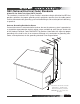
2 Play a test tone or low bass music 3 1 Place the subwoofer in the listening position Walk around the room and see where the bass has the best performance. That’s where your subwoofer belongs! Notice where in the room the bass output from the subwoofer sounds the loudest. Shut things down and install the subwoofer there. This is the best position for the subwoofer. The bass will sound the best when you are sitting in your normal listening position.
Remote Control Codes Audio Components ADC 007 Adcom 082, 092, 225, 161, 269 Aiwa 018, 104, 170, 202, 203, 213, 211, 188 Akai 138, 189 AMC 125, 126, 167, 128, 258, 281, 282 Amend 054 AMX 196 Angstrom 142 Arcam 141 Audio Access 147 Audio Alchemy 135 Audio Design 194, 221, 011 Audio Ease 021, 196, 207 Audio File 071 Audio Matrix 167 Audio Source 273 Audio Technica 134 B&K 096, 097 Bose 070, 170, 224 Bryston 023 Carver 006, 028, 061, 071, 201, 214, 226, 180, 185, 022, 029, 077, 284 Casio 076 Chiro 140 Cinema So
JVC 185 Kenwood 185 Lite-Touch 208 Lutron 077, 158, 159 Makita 186, 201 Mindpath 205 Niles 160, 187 NSM 161 Piano Disc Plus 085 Philips 090 Polk Audio 162 Replay 075 Russound 081 Scientific Atlanta 156, 163 Sima 082 Solo Electronics 207 Somfy 078, 079 Sony 104, 164, 165, 166 Starcom 153 Turboscan 167 Velodyne 203 X-10 093, 183 Xantech 168, 169, 170, 171, 172, 188, 189 General Instruments 074, 103, 104 GNC 099 Golden Channel 030 Hamlin 049, 050, 055 Hitachi 055, 103 Jerrold 002, 003, 004, 008, 009, 010, 013
Philips 041, 044 Pioneer 010, 020, 025, 056, 174, 175, 176 Proceed 239 Proton 044, 107, 228 Quasar 103, 008 Radio Shack 182 RCA 017, 042, 150 Realistic 042, 050, 051, 102, 181, 182, 187 Rotel 044, 107, 161, 178, 250 SAE 044, 107 Sansui 044, 069, 107, 128, 171, 190, 125 Sanyo 050 Scott 069, 102 Sharp 026, 031, 051, 066 Sherwood 003, 019, 051, 096, 112, 115, 119, 166 Signature 033 Sony 048, 081, 097, 126, 133, 177, 225, 226, 164 Soundesign 251 Sumo 155 Sylvania 044, 107 Symphonic 052, 181 Taekwang 195, 085 Ta
Panasonic 142, 060 Pansat 121 Personal Cable 117 Philips 071, 152, 153 PL 023, 026 President 019, 102 Primestar 110, 030 Prosat 072 Proscan 151, 106, 150 RCA 151, 106, 150 Realistic 043, 074 Samsung 123 Satellite Service 028, 035, 047, 085 Sony 103 Starcast 041 Superguide 020, 124, 125 Teecom 023, 026, 075, 087, 088, 090, 107, 130, 137 Toshiba 002, 127 T own & Country 023, 026 Uniden 016, 025, 042, 043, 044, 045, 048, 049, 078, 079, 080, 086,101, 135, 136 Viewstar 115 Winegard 128, 146 Zenith 081, 082, 083,
NAD 015, 025 NEC 132, 130, 134, 197, 040, 016, 024, 056, 019 Nikei 043 Onking 043 Onwa 043 Optonica 019, 081 Orion 096 Panasonic 034, 056, 080, 092, 164 Philco 197, 003, 024, 056, 059, 060, 063, 064, 164, 004 Philips 197, 003, 004, 005, 038, 059, 093, 164, 127 Pioneer 197, 018, 023, 025, 116, 135, 190 Portland 004, 143 Proscan 144, 160, 161, 165, 167 Proton 004, 058, 131, 143, 171, 173, 193 Quasar 034, 056, 092 Radio Shack 019, 043, 143, 004, 127 RCA 160, 161, 165, 065, 156, 144, 197, 004, 023, 024, 056, 07
Philips 031, 034, 054, 067, 071, 101 Pilot 101 Pioneer 013, 021, 048 Portland 108 Pulsar 072 Quartz 002, 014 Quasar 066, 145, 075 Radio Shack 123 RCA 013, 020, 041, 107, 109, 140, 144, 145, 147, 034, 040, 158 Realistic 003, 008, 010, 014, 031, 034, 040, 053, 054, 101 Rico 058 Runco 148 Salora 014 Samsung 032, 040, 066, 102, 104, 107, 109, 112, 113, 115, 120, 122, 125 Sansui 022, 043, 048, 135 Sanyo 003, 007, 010, 014, 134, 102 Scott 017, 037, 112, 129, 131 Sears 003, 008, 009, 010, 013, 014, 081, 101, 017,
Troubleshooting Guide The Emotiva DMC-1 is expertly designed and built to provide years of trouble-free performance. Most problems that occur can usually be solved by checking your setup or making sure that the audio and video components connected to the processor are on and fully operational. The following information will help you deal with common setup problems you may experience during normal use of your unit. If problems persist, contact your Emotiva Dealer for help.
Poor FM Reception The antenna may be incorrectly attached. Station not correctly tuned in, weak or off the air. You can improve reception by using external antennas. Some cable TV feeds also offer FM reception. Input Selection Problems If you find that certain inputs cannot be selected, Check the INPUTS menu of the OSD (page 53), and make sure that the input has not been disabled in that particular Zone.
Noise bursts are heard when DTS encoded CDs or LDs are played. Compressed DTS data uses the normal digital audio tracks of CDs and LDs. This analog noise may be heard in your system before the DTS digital signal is locked on, or it may appear as a background hiss. To reduce or prevent this noise, disconnect any analog connections to your CD, DVD, or Laserdisc players. Just use the Digital connections and see if this addresses the problem.
ZONE 2 Not Working See pages 43 and 55 Zone 2 is set “disabled” from the factory, so you must use the OSD Zone 2 menu on page XX to enable it when you are ready to use it. This enables Zone 2, but it does not turn it on. Once Zone 2 is enabled, use the remote control’s Zone 2 device button, followed by the Power button to turn Zone 2 on. Alternatively, press the front panel Zone 2 button, followed by the main Power button.
the same time. The DMC-1 will power on and cycle through the display. Keep holding the buttons down until “Resetting to Factory Defaults” appears in the front panel display. When the DMC-1 has been reset, it will shut off. Turn the DMC-1 back on and it will go to the default screen. It has now been reset. If the DMC-1 has to be reset regularly, you should invest in a good quality AC line conditioner or contact Emotiva for technical support.
Other Probable Causes of Noise Speaker noise may also be caused by interference or noise on your AC line. Make sure there are no large appliances sharing the line, or halogen lamps or light-dimming Triac devices. Try connecting your system to another AC socket on a separate line. If the hum is heard from within the DMC-1 and not through the speakers, this may also be caused by interference on the AC or DC lines. The power transformers may turn this interference into an audible noise.
Favorite Settings Log You can use this section to log your favorite settings from various OSD menus and other preferences controlled by the DMC-1. This will come in handy if the unit is ever powered down for transport or in the event loss of power is unintentional. TONE BASS TREBLE LEVEL (in dB) Tone Settings You can reference the TONE SETTINGS on page 53 of this manual. MAIN ZONE SETTINGS POWER UP SOURCE POWER UP VOL. MODE POWER UP VOL. LEVEL MAX.
CONTROL SETTINGS RS-232 PORT REAR MAIN I/R REAR ZONE 2 I/R FRONT PANEL I/R SELECTION Control Settings You can reference the CONTROL SETTINGS on page 62 of this manual. VIDEO SETTINGS OSD VOL POP-UP OSD SOURCE POP-UP OSD MODE POP-UP VIDEO DEFAULT VID2 / MON2 VIDEO DELAY SELECTION Video Settings You can reference the VIDEO SETTINGS on page 61 of this manual. Input Settings, Remote Codes, and Speaker Settings tables can be found on the next page.
Input Settings and Remote Codes You can reference the INPUT SETTINGS on page 53 of this manual. REMOTE CODES are found on pages 78-83. Check off the appropriate boxes, fill in the appropriate information and indicate levels where necessary. INPUT JACK NAME GAIN MAIN VIDEO TRIG. ZONE MAKE & TRIM ZONE TYPE RLY. 2 MODEL REMOTE CODES NORM VOL. DVD CD 8-CH SAT VID 1 VID 2 TUNER TAPE PHONO SPEAKER Settings You can reference the SPEAKER SETTINGS on pages 56-60 of this manual.
Technical Specifications Line Level Inputs Sensitivity (for 0.5 V output): Phono: Frequency Response: +/- 0.5 dB: Signal to Noise Ratio (relative to 2V out): Distortion (THD): Separation (@1kHz): Tone Control Bass: Treble: FM Tuner Section FM Range: 125mV 1.6mV 20 Hz-20 kHz Analog 97 dB Digital 105 dB <0.03% 70dB +/- 10dB +/- 10dB 87.5-108MHz 0.2MHz Steps Usable FM Sensitivity (Mono) 1.6uV@75 Ohms @75kHz 15.2 dBf (DEV 30dB) 50dB Quieting Sensitivity (Stereo) 31.6 uV @75 Ohms 41.
Licensing and Trademark Disclosures DTS Disclosure This product is manufactured under license from Digital Theater Systems, Inc. US Patent No 5,451,942, 5,956,674, 5,974,380, 5,978,762 and other worldwide patents issued and pending. “DTS”, “DTS-ES Extend Surround”, and “Neo:6” are trademarks of Digital Theater Systems, Inc. Copyright 1996-2004 Digital Theater Systems, Inc. All Rights Reserved. Dolby Disclosure This product is manufactured under license from Dolby Laboratories.
Limited Warranty Emotiva is proud to design and manufacture quality products for the home audio and home theater enthusiast. Your DMC-1 preamplifier has been crafted to perform flawlessly for many years. As a result of this quality and craftsmanship, Emotiva offers the following warranty to owners of the DMC-1. Emotiva Audio warrants the DMC-1 to be free of defects in materials and workmanship for a period of FIVE YEARS from the original date of purchase.
Emotiva 27901 Smyth Drive Valencia, CA. 91355 Tel Fax Website - (877) 366-8324 (877) EMO-TECH (661) 775-9462 www.emotivaaudio.com Tel Website - Exclusive Distributor AV123 (877) 543-7500 www.av123.com Rev 3.