
User`s guide


Table Of Contents
- TABLE OF CONTENTS
- Safety Precautions
- NEC (National Electrical Code) Standards
- A Note for the Cable Television (CATV) Installer
- Antenna Grounding Outside the House
- Thank You for your DMC-1 Purchase
- Unpacking the DMC-1
- Recording the Serial Number
- Features of the DMC-1 A/V Controller
- DMC-1 Front Panel Features
- Power Button
- IR Receiver Window
- Processor Display
- Z II (Zone 2)
- Input Select Buttons
- MODE UP/DOWN (Mode Buttons)
- AM/FM Tuner Controls
- Tone Controls
- Signal Processing Indicator Lights
- Additional Front Panel Features
- COM/RECV
- ZONE TWO POWER
- ZONE TWO ADJUST
- SIDE AXIS
- PANEL DIM Button
- MUTE Button
- DMC-1 Rear Panel Layout
- Component Video In
- Component Video Out
- Audio/Video Inputs
- Audio/Video Outputs
- Triggers and Relay
- Infrared (IR) Inputs
- RS-232 Port
- 8-CH Analog Input
- Main Audio Outputs
- XLR Audio Outputs
- Audio Inputs
- Ground Screw
- FM Antenna
- AM Antenna
- Side-Axis Outputs
- Stereo Outputs
- Audio Outputs
- IEC Line Cord Socket
- Digital Inputs
- Digital Output
- IEEE-1394 "Firewire" Port
- Installation and Connections
- AC Power Considerations
- Connection Tips for Superior Sound
- Connection Tips for Video Quality and Flexibility
- What is Composite Video?
- What is S-Video?
- What is Component Video?
- Video Up Conversion
- Video Output to the Main Screen and OSD
- Zone Specific Turn-On Triggers
- Connection Diagrams
- Connecting a DVD-Video Player (Analog Audio and Composite Video)
- Connecting a DVD-Video Player (Digital Audio and Component Video)
- Connecting to the TV or Projector using Component Video
- Connecting a VCR (Analog Audio and Composite Video)
- Connecting a CD Player (Analog Audio)
- Connecting a Cassette Tape or DAT Deck
- Connecting the 8-Channel Analog Inputs
- Connecting the AM and FM Antennas
- Connecting an Amplifier (MAIN ZONE)
- Connecting an Amplifier (ZONE 2)
- Connecting an Amplifier (ZONE 2)
- Overview of the DMC-1 Remote
- Button Layout
- Button and Display Light
- LCD Display
- DEVICE Buttons
- PAGE Button
- MAIN Button
- FAV Button
- JOYSTICK PAD
- M1, M2 and M3 Macro Buttons
- Quick Start Setup Instructions
- Adding Batteries to the Remote Control
- Quick Start Instructions for DMC-1 Setup
- Operation of the DMC-1 using the Remote
- Turning on the MAIN Zone
- Turning on ZONE 2
- Programming and Configuring YOUR Components
- P-PRO
- LEARN
- EDIT
- FAV
- PUNCH
- ERASE
- LIGHT
- MACRO
- RECAL (Recall)
- CLONE
- The On-Screen Display (OSD) Functions
- Video Connections
- OSD Activation
- Quick Access to Information
- OSD Menus
- How to Navigate the OSD Menus
- TRIM Menu
- MODES Menu
- Dynamic Range
- Pro Logic IIx Sub Menu
- DTS LFE
- DTS Neo:6
- Party
- Jazz Club Ambience
- TONE Menu
- INPUTS Menu
- INPUT CONFIGURATION MENUS (The example shows the DVD menu)
- Tuner Preset Menu
- Saving AM/FM Presets
- SETTINGS Menus
- MAIN ZONE Menu
- ZONE 2 Menu
- SPEAKERS Menu - SIZE
- SPEAKERS Menu - POSITION
- SPEAKERS Menu - CALIBRATION
- Crossover Adjustment
- Subwoofer Mode
- VIDEO Menu
- SOFTWARE Menu
- CONTROL Menu
- Special Features of the Emotiva DMC-1
- Bass Management
- Surround Modes for 2 Channel Source Material
- Surround Modes for Multi-Channel Sources
- Tuner Operation
- Recording
- Zone 2 Operation
- Speaker Placement Tips
- Tips Before You Begin
- The Front Speakers
- The Center Speaker
- Side-Axis Speakers
- The Surround Speakers
- Surround Back Speakers
- Subwoofer Location
- Remote Control Codes
- Audio Components
- Auxiliary Devices
- Cable Boxes
- CD Players
- DVD Players
- Laserdisc Players
- Satellite/DSS Receivers
- Tape Decks
- Televisions
- VCRs
- Troubleshooting Guide
- No Sound (from one or more full range speakers)
- No Subwoofer (or poor output)
- Poor AM Reception
- Poor FM Reception
- Input Selection Problems
- There is No TV Picture
- No Tone Control Functions
- No Dolby Digital or DTS Playback
- No On Screen Display
- Remote Won't Learn Commands or Codes
- Remote Not Working
- ZONE 2 Not Working
- External Amplifier(s) Shut Down (Often or Prematurely)
- DMC-1 "Locks Up" (No Response)
- Reset Procedure
- Problems Updating DMC-1 Firmware
- "Hum" Noises
- Other Probable Causes of Noise
- Favorite Settings Log
- Tone Settings
- Main Zone Settings
- Zone 2 Settings
- Mode Settings
- Control Settings
- Video Settings
- Input Settings and Remote Codes
- SPEAKER Settings
- Technical Specifications
- Licensing and Trademark Disclosures
- DTS Disclosure
- Dolby Disclosure
- Apple Disclosure
- Emotiva Disclosure
- Limited Warranty
Page 34
T
R
IG
G
E
R
IN
P
U
T
O
N
S
I
G
-
N
A
L
T
R
I-
G
G
E
R
T
1
5
A
L
2
5
0
V
A
C
1
2
0
V
6
0
H
z
U
N
B
A
L
A
N
C
E
D
I
N
P
U
T
B
A
L
A
N
C
E
D
I
N
P
U
T
O
U
T
P
U
T
U
N
B
A
L
A
N
C
E
D
I
N
P
U
T
B
A
L
A
N
C
E
D
I
N
P
U
T
O
U
T
P
U
T
U
N
B
A
L
A
N
C
E
D
I
N
P
U
T
B
A
L
A
N
C
E
D
I
N
P
U
T
O
U
T
P
U
T
U
N
B
A
L
A
N
C
E
D
I
N
P
U
T
B
A
L
A
N
C
E
D
I
N
P
U
T
O
U
T
P
U
T
U
N
B
A
L
A
N
C
E
D
I
N
P
U
T
B
A
L
A
N
C
E
D
I
N
P
U
T
O
U
T
P
U
T
U
N
B
A
L
A
N
C
E
D
I
N
P
U
T
B
A
L
A
N
C
E
D
I
N
P
U
T
O
U
T
P
U
T
U
N
B
A
L
A
N
C
E
D
I
N
P
U
T
B
A
L
A
N
C
E
D
I
N
P
U
T
O
U
T
P
U
T
D
e
s
ig
n
e
d
in
U
S
A
B
u
ilt w
ith
p
r
id
e
in
C
h
in
a
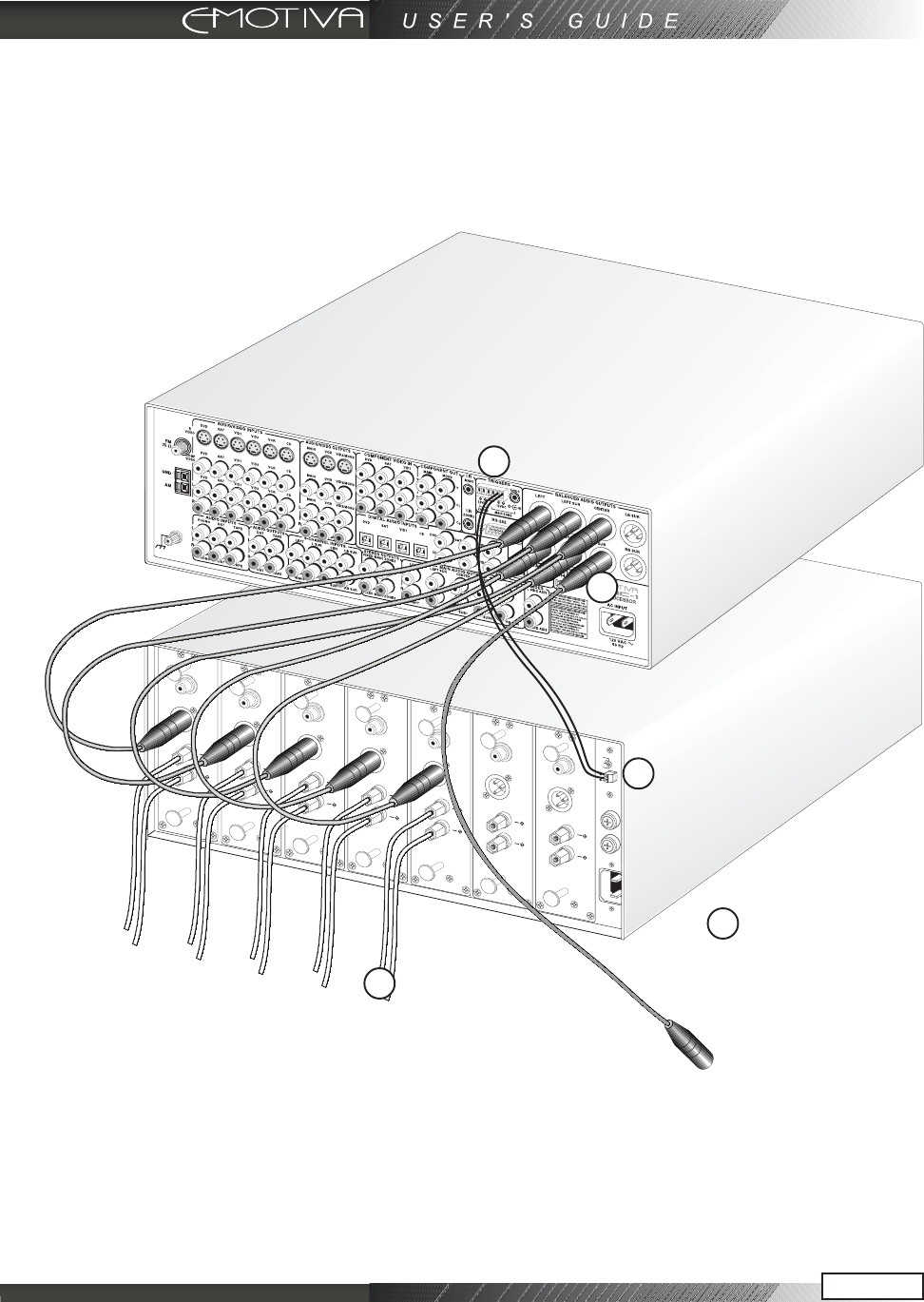
Connecting an Amplifier (MAIN ZONE)
This configuration shows the MAIN ZONE connections to a multi-channel amplifier. You may
use single ended RCA audio cables or the preferred balanced XLR audio connections. The
advantage of the XLR balanced connections is that they have a much higher rejection to any
radiated noise from AC line cord interference. Also note the connection of the 12 VDC trigger
to turn the amplifier on.
In this configuration the DMC-1 is connected to 5 channels of amplification via balanced XLR
connections. The sixth output would connect to the input of a powered subwoofer. If using
more than one subwoofer, use the pass through output on one subwoofer to route the input
signal to the additional subwoofer(s). If you choose to connect the remaining two connections
(LEFT and RIGHT SURROUND BACK) you will need a 7 channel amplifier like the one
shown here - the Emotiva MPS-1 - and you must enable the channels through the SPEAKER
SIZE menu of the DMC-1 remote control.
This connector will
plug into the input of
a powered subwoofer
1
1
1
2
By connecting the 12 VDC
trigger, the amplifier will turn
on whenever the DMC-1’s
MAIN ZONE is selected
2