USER’S GUIDE
TABLE OF CONTENTS Safety Precautions ................................................... 6 NEC (National Electrical Code) Standards..............................8 A Note for the Cable Television (CATV) Installer ................................................... 8 Antenna Grounding Outside the House ................................................................. 8 Thank You for your MPS-1 Purchase....................... 9 Unpacking the MPS-1..............................................
Connection Tips for Superior Sound.....................................20 Connection Diagrams .............................................................21 Unbalanced Connections....................................................................................... 21 Balanced Connections ........................................................................................... 22 12V Trigger Connections .......................................................................................
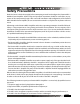
Safety Precautions Read this Owner’s Guide thoroughly before attempting to install and configure the Emotiva MPS-1 Modular Power Amplifier. All the safety and operation instructions should be read before any operation of the component(s) begin. After successful installation and configuration of the Emotiva MPS-1 Modular Power Amplifier, be sure to retain this manual in a safe place for any future reference needs.
The user should not attempt to service the MPS-1 Modular Power Amplifier beyond the means described in this Owner’s Guide. All other servicing should be referred to qualified service personnel. To prevent electric shock, do not use this polarized plug with an extension cord, receptacle or other outlet unless the blades can be fully inserted to prevent blade exposure.
NEC (National Electrical Code) Standards A Note for the Cable Television (CATV) Installer This reminder is to call the CATV system installer’s attention to Article 820-40 of the NEC that provides guidelines for proper grounding and in particular, specifies that the cable ground shall be connected to the grounding system of the building as close to the point of cable entry as practical.
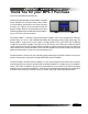
Thank You for your MPS-1 Purchase Dear Home Entertainment Enthusiast, Thank you for purchasing the Emotiva MPS-1 Modular Power Amplifier. We sincerely believe that it offers you outstanding performance and value. Emotiva products are engineered and produced with the highest quality materials and incorporate the latest technology. We think you will find the Emotiva MPS-1 meets or exceeds your expectations. The Emotiva MPS-1 is a flexible, high perfornmance amplifer.
Unpacking the MPS-1 The Emotiva MPS-1 Modular Power Amplifier should reach you in flawless condition. If you notice any shipping damage or other issues upon unpacking the unit, please contact your Emotiva Retailer immediately. Gently lift out the unit and remove all the packing material and accessories. It is important to save all the packing materials and the box in case your Emotiva MPS-1 ever needs to be moved or shipped back to the factory for service. Make sure that you keep your sales receipt.
Emotiva MPS-1 Modular Power Amplifier Modular Professional Power Amplifier Features • Audiophile quality, modular power amplifier • True card cage design can accommodate up to seven independent 200 watt mono block power modules - power modules glide in and out on Nylon rails • Power modules feature independent 350VA, low noise toroid power transformers w/ high speed rectifiers and 48,000uF of storage per channel for a 336,000uF total, across seven independent channels • High efficiency Class H power amplifi
MPS-1 Front Panel Features 3 1 1 Power Button This turns the main power to the MPS-1 on or off. It is a main power button, but it is not required to turn this on and off each time the MPS-1 is used. When enabled, the AUTO ON/OFF MODE will automatically switch the amplifier on when an audio signal comes from a source or control unit (such as a preamplifier). The TRIGGER MODE will turn the amplifier on when an external source (such as a preamplifier) provides a 5-24 VDC input on the trigger terminals.
MPS-1 Finished Rear Panel Layout 4 5 6 7 1 2 3 8 Note: Before connecting any components to the MPS-1, the individual power modules must first be installed into the chassis. Please see pages 15-17 for details on the power module installation. 1 Unbalanced RCA Inputs The MPS-1 has one unbalanced RCA input available for each amplifier channel module. Connect this to the corresponding RCA jack on your preamplifier to provide signal to the amplifier channel. See page 21 for a connection diagram.
4 Turn On Selector Switch Turn On Selector Switch This switch allows you to select how the amplifier will turn on and off. In the ON (Up) position, the switch on the front of the amplifier is the method you will use to power up and power down the amplifier. Please note that in this configuration, you must manually power up and power down the amplifier each time you use it or it will have unnecessary standby current draw.
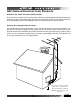
Installation and Connections Observe the following precautions when choosing a location for your Emotiva MPS-1: 1) Protect it from prolonged exposure to direct sunlight and other direct sources of heat, such as heating vents and radiators. 2) Do not expose the unit to rain or moisture. If fluid or a foreign object should enter the unit, immediately turn off the power and contact your Emotiva Dealer. 3) Avoid excessive exposure to extreme cold or dust. 4) Do not place heavy objects on top of the unit.
Orienting the Module to the MPS-1 Chassis Upon removing the EPM-300 power module from the packaging, you must orient which is the “top” and “bottom” as well as which is the “front” and “back”. The top has a single nylon rail while the bottom has two nylon rails. It is important that the module be placed in so that the rails on the top and bottom align with the corresponding “rail channels” in the MPS-1 chassis.
Inserting the EPM-300 Module CAUTION: Make sure the MPS-1 chassis is NOT CONNECTED to line voltage during the installation of the power modules! 1 Gently align the rails and slide the Power Module into place 2 Once installed, attach (4) #2 Phillips screws to secure the Power Module 1 Single Nylon Rail (Top) Front MPS-1 Chassis 2 For proper installation of the power module, the nylon rail guides must be aligned with the metal rails channels inside the MPS-1.
MPS-1 Installation Accessories The MPS-1 Modular Power Amplifier comes with some additional installation accessories that make the component fit into virtually any installation theme. Piano Black Wood Side Panels The MPS-1 comes with attractive wood side panels in a stunning piano black lacquer finish. As this electronic component is going to be in many homes alongside equally nice furniture, the side panels allow the MPS-1 to look a little more like it belongs in the room.
AC Power Considerations Ensure that the unit is plugged into an outlet capable of supplying the correct voltage and current specified for your model. Remember to account for the electrical power that other components will require if they share a common wall socket or electrical circuit. The majority of household electrical sockets in places other than the kitchen and garage are 15 amperes maximum. Most DVD players and other source components are fairly low current items.
It is important to observe polarity so that the speaker wire connects to the red and black terminals on the amplifer and the corresponding terminals at the speaker. Also make sure that the positive speaker wires do not touch the negative speaker wires, or any chassis metal. This will cause a short circuit and activate the protection circuitry. Automatic Operation of the Cooling Fan(s) Each power module in the MPS-1 is equipped with a cooling fan to maintain a safe operating temperature.
Connection Diagrams Unbalanced Connections If your preamplifier has RCA outputs, it can be connected to the amplifier inputs as shown. The amplifier will boost the preamplifier’s output, up to a level suitable for driving speakers. Make sure that the positive speaker wires do not touch the negative speaker wires, or any chassis metal. This will cause a short circuit and may activate the protection circuitry.
Balanced Connections If your preamplifier has balanced XLR outputs, it can be connected to the amplifier inputs as shown. The amplifier will boost the preamplifier’s output, up to a level suitable for driving speakers. The overwhelming advantage of using the balanced XLR inputs is that there is superior noise rejection over the common RCA type connections. Make sure that the positive speaker wires do not touch the negative speaker wires, or any chassis metal.
12V Trigger Connections The 12 VDC trigger connection shown can be used to turn the amplifier on when the preamplifier turns on. This trigger will actually trigger with any switched DC Voltage from 5-24 VDC, however the majority of home theater components use a standard 12 VDC trigger connection for this function. This is the preferred connection as it has the greatest degree of reliability. Never switch anything that plugs directly into the wall with this trigger connection.
Series and Parallel Speaker Connections Whenever connecting more than one speaker per channel to an amplifier (regardless of the brand), you must consider the way in which the amplifier will be impacted by adding the additional speaker(s). Additionally, speakers with dual voice coils also apply to this consideration. Two voice coils in a single speaker also cause different reactions from an amplifier depending on the way in which they connect to the amplifier.
Parallel A parallel circuit is established when voice coils are connected in a way that there are multiple paths for audio signals to flow “in” and multiple paths for audio signals to flow “out”. When speakers are connected in parallel, the total resistance at the amplifier is proportionally divided based on the value of each individual voice coil resistance. The term “divided” simply means all of the values together in parallel are a SMALLER value than each all by itself.
Speaker Placement Tips Tips Before You Begin Read this section thoroughly. There are a number of ways in which it may seem aesthetically pleasing to place speakers in a room that will ultimately result in a sound quality compromise. The placement of speakers is equally as important as the room itself. While there may be very little you can do about the room where your home theater is installed, you can choose placement of speakers within that room to maximize the sound quality of the system.
The Front Speakers You should closely follow the placement recommendations of your speaker manufacturer, with the addition of the following points: • The left and right front speakers should be positioned so that your TV is exactly centered between them. This will help focus your attention towards the screen. • For the best overall imaging, the left speaker should be set exactly the same distance and angle away from your listening position as the right speaker.
Side-Axis Speakers Some preamplifier processors feature side-axis channels which are matrixed and derived from the left and right front channels, so they are available in stereo as well as surround modes. If available as a feature, the processor should have a set-up menu to turn the SIDE-AXIS channels ON or OFF. In the diagram to the left, typical placement of side-axis speakers is depicted by the speakers that appear to be “suspended” where walls are in the room.
Surround Back Speakers Many preamplifier processors feature additional outputs for surround back speakers. These create a wonderful sense of realism in surround effects during playback of Dolby Digital EX, Dolby Pro Logic IIx, and DTS ES. Ideally, all the surround speakers should be of the same make and model as the surround speakers, and fitted at similar heights to produce a smooth continuous sound field.
2 Play a test tone or low bass music 3 1 Place the subwoofer in the listening position Walk around the room and see where the bass has the best performance. That’s where your subwoofer belongs! Notice where in the room the bass output from the subwoofer sounds the loudest. Shut things down and install the subwoofer there. This is the best position for the subwoofer. The bass will sound the best when you are sitting in your normal listening position.
Troubleshooting Guide The Emotiva MPS-1 is expertly designed and built to provide years of trouble-free performance. Most problems that occur can usually be solved by checking your setup or making sure that the audio and video components connected to the amplifier are on and fully operational. The following information will help you deal with common setup problems you may experience during normal use of your unit. If problems persist, contact your Emotiva Dealer for help.
speakers play the full range. Make sure that the preamplifier has been correctly set. If you are not using a subwoofer, set the speaker options to “Large” where possible. • Check that the speaker wires have been connected correctly: Make sure that the positive of each speaker connects to a positive output of the amplifier, and the negative of each speaker connects to a negative output. If one speaker is wired incorrectly, than it will be “out of phase” with the others, resulting in poor bass performance.
• Check that the interconnect cables to the amplifier do not have any broken connections. The best way to do this is to substitute a known good connection for the suspect connection. If you reverse the cables and the problem goes away, the cable may be damaged or broken. This is possible even if you can’t physically see the break as the strain for pulling on audio cables can sometimes break the wire internally. Ground loop isolators are available for audio lines and video devices.
Technical Specifications EPM-300 Power Module Rated Power Output: 8 Ohms: 200W RMS 4 Ohms: 300W RMS Stable to 2 Ohms XLR Inputs Frequency Response: +/- 0.1 dB: +/- 3 dB: Power Requirements (All Channels Driven) 120VAC, 60Hz, 4200W 20 Hz-20 kHz 10 Hz-100 kHz Pin #3 Pin #1 Power Consumption (Standby) (At Idle) Signal to Noise Ratio (Un-weighted): 100 dB Distortion (THD): (20Hz-20kHz): <0.
Limited Warranty Emotiva is proud to design and manufacture quality products for the home audio and home theater enthusiast. Your MPS-1 Modular Power Amplifier has been crafted to perform flawlessly for many years. As a result of this quality and craftsmanship, Emotiva offers the following warranty to owners of the MPS-1. Emotiva Audio warrants the MPS-1 to be free of defects in materials and workmanship for a period of FIVE YEARS from the original date of purchase.
Emotiva Disclosure Copyright 2004-2006 Emotiva Audio Corporation All Rights Reserved. Emotiva reserves the right to make improvements to its products at any time. Therefore, the specifications of the product and the specific details of this manual are subject to change at any time.
Emotiva 106 Mission Court, Suite 101 Franklin, TN 37067 Tel Fax Website - (615) 771-1224 (877) EMO-TECH (615) 771-1128 www.emotiva.com Rev 3.