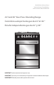
Installation Instructions Instructions d’installation Instrucciones de instalación 24" and 36" Gas Free-Standing Range Cuisinière autoportante gaz de 24" et 36" Estufa independiente gas de 24" y 36" MIN 150 MAX 180 210 240 IMPORTANT: Save for local electrical inspector’s use. IMPORTANT: Conserver pour consultation par l’inspecteur local des installations électriques. IMPORTANTE: Guárdelo para uso del inspector eléctrico local.
TABLE OF CONTENTS RANGE SAFETY.................................................................................................... 2 INSTALLATION REQUIREMENTS.......................................................................... 4 Tools and Parts................................................................................................................ 4 Location Requirements.................................................................................................. 6 Electrical Requirements..
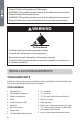
RANGE SAFETY Your safety and the safety of others are very important. We have provided many important safety messages in this manual and on your appliance. Always read and obey all safety messages. This is the safety alert symbol. This symbol alerts you to potential hazards that can kill or hurt you and others. All safety messages will follow the safety alert symbol and either the word “DANGER,” “WARNING” or “CAUTION.” These words mean: DANGER An imminently hazardous situation.
WARNING Fire Hazard If the information in this manual is not followed exactly, a fire or explosion may result causing property damage, personal injury or death. - Do not store or use gasoline or other flammable vapors and liquids in the vicinity of this or any other appliance. - WHAT TO DO IF YOU SMELL GAS • Do not try to light any appliance. • Do not touch any electrical switch. • Do not use any phone in your building. • Clear the room, building, or area of all occupants.
State of California Proposition 65 Warnings: WARNING: This product contains one or more chemicals known to the State of California to cause cancer. WARNING: This product contains one or more chemicals known to the State of California to cause birth defects or other reproductive harm. WARNING Tip Over Hazard A child or adult can tip the range and be killed. Connect anti-tip bracket to rear range foot. Reconnect the anti-tip bracket, if the range is moved.
5
LOCATION REQUIREMENTS VENTILATION IMPORTANT: Observe all governing codes and ordinances. Do not obstruct flow of combustion and ventilation air. • It is the installer’s responsibility to comply with installation clearances specified on the model/serial rating plate. The model/serial rating plate is located on the left-hand side of the oven frame. Open oven door to view label. See label on back panel of range for additional element and oven power ratings.
DIMENSIONS Product and Opening Opening dimensions shown are for 25" (64.0 cm) countertop depth, 4" (61.0 cm) base cabinet depth and 36" (91.4 cm) countertop height. 36" 24" 5.9" (15 cm) Min. 5.9" (15 cm) Min. 30" (76 cm) Min. 30" (76 cm) Min. a a ed ed c c b b Model Size A. Depth w/ Handle B. Width C. Depth D. Height to top of Cooktop E. Height Overall 24" 251/5" (64.28 cm) 232/5" (60 cm) 233/5" (60 cm) 36" (91 cm) 373/5" (95.5 cm) 36" 251/5" (64.
Back of Range a a Gas Line from Range b Power Cord b Power Supply IMPORTANT: An electrical outlet in the floor, may be either recessed or surface mounted, but an electrical outlet in the wall must be recessed to make the connection. For Direct Wiring, the electrical box should be mounted to the wall. a b h g d e a 24" Model - 232/5" (60 cm) 36" Model - 352/5" (90 cm) b 111/2" (29.2 cm) c 6" (15.2 cm) d 71/4" (18.4 cm) e 3" (7.
ELECTRICAL REQUIREMENTS WARNING Electrical Shock Hazard Plug into a grounded 3 prong outlet. Do not remove the ground prong from the power cord plug. Do not use an adapter. Do not use an extension cord. Failure to do so can result in death, fire or electrical shock. IMPORTANT: The range must be electrically grounded in accordance with local codes and ordinances, or in the absence of local codes, with the National Electrical Code, ANSI/NFPA 70 or Canadian Electrical Code, CSA C22.1.
NOTE: The metal chassis of the range must be grounded in order for the control panel to work. If the metal chassis of the range is not grounded, no keypads will operate. Check with a qualified electrician if you are in doubt as to whether the metal chassis of the range is grounded. GAS SUPPLY REQUIREMENTS WARNING Explosion Hazard Use a new CSA International approved gas supply line. Install a shut-off valve. Securely tighten all gas connections.
LP gas conversion: IMPORTANT: Conversion must be done by a qualified service technician. No attempt shall be made to convert the appliance from the gas specified on the model/serial rating plate for use with a different gas without consulting the serving gas supplier. See “Gas Conversions” section. GAS SUPPLY LINE Provide a gas supply line of 3/4" (1.9 cm) rigid pipe to the range location. A smaller size pipe on longer runs may result in insufficient gas supply.
Rigid pipe connection: The rigid pipe connection requires a combination of pipe fittings to obtain an in-line connection to the range. The rigid pipe must be level with the range connection. All strains must be removed from the supply and fuel lines so range will be level and in line. GAS PRESSURE REGULATOR The gas pressure regulator supplied with this range must be used.
INSTALLATION INSTRUCTIONS IMPORTANT: This appliance shall be installed only by authorized persons and in accordance with the manufacturer’s installation instructions, local gas fitting regulations, municipal building codes, electrical wiring regulations, local water supply regulations. STEP 1 - UNPACK RANGE WARNING Excessive Weight Hazard Use two or more people to move and install range. Failure to do so can result in back or other injury. 1. Remove shipping materials, tape and film from the range.
NOTE: 24" model uses (2) screws and the 36" model uses (4) screws 24" Model b a 36" Model a Backsplash -Back Edge b Backsplash - Bottom Edge b a a Backsplash -Back Edge b Backsplash - Bottom Edge 3. Insert the two screws (one on each side) through the back edge of the backsplash and into the cooktop. Tighten completely.
STEP 3 - INSTALL ANTI-TIP BRACKET IMPORTANT: This insert replaces the directions for “Installing the Anti‑Tip Bracket” and “Installing the Range” found in the 24" and 30" Electric Free‑Standing Range Installation Instructions for Models HCR2250AES and HCR3560AES. INSTALL ANTI-TIP BRACKET WARNING Tip Over Hazard A child or adult can tip the range and be killed. Connect anti-tip bracket to rear range foot. Reconnect the anti-tip bracket, if the range is moved.
3. Using the anti-tip bracket as a template, mark the two holes for either a Floor Wood, Floor Concrete, or Wall installation, as shown. a b a Distance from Adjacent Cabinet (³⁄₈" to ¹⁄₂" [0.95 to 1.27 cm]) b Wall Holes c Concrete Floor Holes d Wood Floor Holes e Rear Range Foot e dc 4. Drill two pilot holes where marked. Follow the instructions specific to your construction. NOTE: A nail or awl may be used to create a pilot hole, if a drill is not available.
STEP 4 - MAKE GAS CONNECTION WARNING Explosion Hazard Use a new CSA International approved gas supply line. Install a shut-off valve. Securely tighten all gas connections. If connected to LP, have a qualified person make sure gas pressure does not exceed 14" (36 cm) water column. Examples of a qualified person include: licensed heating personnel, authorized gas company personnel, and authorized service personnel. Failure to do so can result in death, explosion or fire.
CONNECT GAS LINE FROM GAS PRESSURE REGULATOR TO GAS SUPPLY: 1. Apply pipe-joint compound made for use with LP gas to the tapered (NPT) threads of both adapters d supplied with gas line kit. 2. Attach one adapter to the gas pressure regulator and the other to the gas shutoff valve and tighten both. NOTE: Do Not rotate the gas pressure regulator. 3. Attach the flexible gas line c to adapters d, one adapter at each end. IMPORTANT: All connections must be wrench tightened (requires two 10" adjustable wrenches).
STEP 5 - MAKE ELECTRICAL CONNECTION WARNING Electrical Shock Hazard Plug into a grounded 3 prong outlet. Do not remove the ground prong from the power cord plug. Do not use an adapter. Do not use an extension cord. Failure to do so can result in death, fire or electrical shock. 1. Slide range close to final location. 2. Plug into a grounded 3 prong outlet.
3. Slowly attempt to tilt the range forward. If you encounter immediate resistance, the range foot is engaged in the anti-tip bracket. Go to Step 8. 4. If the rear of the range lifts more than ½" (1.3 cm) off the floor without resistance, stop tilting the range and lower it gently back to the floor. The range foot is not engaged in the anti-tip bracket. IMPORTANT: If there is a snapping or popping sound when lifting the range, the range may not be fully engaged in the bracket.
STEP 8 - CHECK OPERATION OF ELECTRONIC IGNITION SYSTEM The cooktop and oven burners use electronic igniters in place of standing pilots. When the cooktop control knob is turned to the “ICON” position, the system creates a spark to light the burner. This sparking continues, as long as the control knob is turned to “ICON.” When the oven control is turned to the desired setting, sparking occurs and ignites the gas.
If the low flame needs to be adjusted: a OFF b MAX a Adjustment Screw b Control Knob Stem MIN 1. Light one burner and turn the control knob to the lowest setting. 2. Remove the control knob. 3. Insert a small, flat-blade screwdriver into the adjustment screw, and slowly turn the screw until the flame appearance is correct. • • Open the valve more if the flames are too small or fluttered. Close the valve more if the flames are too large. 4. Replace the control knob. 5.
LP/PROPANE GAS CONVERSION This appliance can be used with Natural Gas or LP/Propane gas. It is shipped from the factory for use with natural gas. A kit for converting to LP gas is supplied with your cooktop. The kit is marked “FOR LP/PROPANE GAS CONVERSION”. When the cooktop is converted for liquid petroleum (LP) gas, the LP gas supply is required to provide a minimum of 10" to a maximum of 14" water column to the cooktop regulator.
36" Burner and Orifice Characteristic Table Burner Position Auxiliary Front R Semi-Rapid Rear L and R Dual Burner Rapid Burner Orifice Gas Pressure Rate Diam. (mm) Type [i.w.c.] [BTU/h] 1.1 NG 4" 5000 0.7 LP (Propane) 10" 5000 1.29 NG 4" 6900 0.8 LP (Propane) 10" 6500 Middle Inner 0.99 x 5 NG 4" 17400 Middle Outer 0.56 x 5 LP (Propane) 10" 15000 Front L 1.45 NG 4" 8200 0.
STEP 1 - ADJUST THE REGULATOR IMPORTANT: Disconnect all electrical power, at the main circuit breaker or fuse box. Shut off the gas supply to the range by closing the manual shut-off valve. 1. Unscrew the regulator cap with the wrench. a a Regulator Cap 2. Remove the retainer pin that is currently positioned for use with Natural Gas. a a Retainer Pin 3. Turn the retainer pin upside down and replace it into the regulator cap. It is now positioned for use with LP gas.
4. Screw the regulator cap back into the regulator and reattach the regulator to the nipple and flare union. STEP 2 - CHANGE BURNER ORIFICES IMPORTANT: Carefully read and observe each orifice label for correct location. See the Burner Chart earlier in this section. NOTE: First remove all orifices and then start replacing them. This will help avoid the possibility that some may not be replaced. 1. Remove the burner grates, burner caps and burner heads. 2. Using a 7 mm nut driver, remove the burner orifices.
Properly Seated Not Properly Seated STEP 3 - ADJUST BURNER FLAMES NOTES: • Turn all burners on highest setting and check the flames. They should be blue in color and may have some yellow tipping at the ends of the flame when using LP gas. Foreign particles in the gas line may cause an orange flame at first, but this will soon disappear. • • Turn the cooktop burner knob to “LO” while observing the flame. Adjustments must be made with two other burners in operation on a medium setting.
2. Remove the control knob. 3. Insert a small, flat-blade screwdriver into the adjustment screw, and slowly turn the screw until the flame appearance is correct. • • Open the valve more if the flames are too small or fluttered. Close the valve more if the flames are too large. 4. Replace the control knob. 5. Test the flame by turning the control from “LO” to “HI,” checking the flame at each setting. 6. Repeat above steps for each burner.