INSTRUCTION MANUAL GAS COOKTOP Appliance Class: 3 Model: 24 " :JZT-HQ4B67AAZXA JZT-HQ4L67AAZXA 30 " :JZT-HQ5B70CAZXA JZT-HQ5L70AAZXA 34 " :JZT-HQ5B90AAZXA JZT-HQ5B90CAZXA JZT-HQ5L90AAZXA 36" : JZT-HQ5B90SAZXA JZT-HQ5L90IAZXA Item : 24 " :EMPV-24GC4B67A EMPV-24GC4L67A 30 " :EMPV-30GC5B70C EMPV-30GC5L70A 34 " :EMPV-34GC5B90A EMPV-34GC5B90C EMPV-34GC5L90A 36" : EMPV-36GC5B90S EMPV-36GC5L90I
Distributed by: Empava Appliances Inc. 15253 Don Julian Rd, City of Industry, CA 91745 USA www.empava.com The instructions shall be marked with directions to the installer to leave them with the appliance and to the consumer to retain them for future reference.
WARNING: This appliance can be used by children aged from 8 years and above and persons with reduced physical, sensory or mental capabilities or lack of experience and knowledge if they have been given supervision or instruction concerning use of the appliance in a safe way and understand the hazards involved. Children shall not play with the appliance. Cleaning and user maintenance shall not be made by children without supervision. If the supply cord is damaged, it must be replaced by the manufacturer.
Contents ◆ Cooktop Description ◆ Important Information ◆ Operation ◆ Maintenance and Cleaning ◆ Troubleshooting ◆ Instructions for the Installer ◆ Important safety requirements ◆ Installation
This appliance shall be installed in accordance with the regulations in force and only used in a well ventilated space. Read the instructions before installing or using this appliance. The installation must conform with local codes or, in the absence of local codes, with the National Fuel Gas Code, ANSI Z223.1/NFPA 54 or,in Canada, the Natural Gas and Propane Installation Code, CSA B149.1.
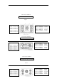
Cooktop Description Operating Instructions: 1.burner 1 — 3400Btu/hr in 45 mm button 5 is for burner 4 2.burner 2 — 12000Btu/hr in 132 mm button 6 is for burner 1 3.burner 3 — 6000Btu/hr button 7 is for burner 3 in 65 mm 4.burner 4 — 10200Btu/hr in 95 mm button 8 is for burner 2 Total heat input: 31600Btu/hr JZT-HQ4B67AAZXA, EMPV-24GC4B67A Figure 1 Operating Instructions: 1.burner 1 — 3400Btu/hr in 45 mm button 5 is for burner 4 2.burner 2 — 12000Btu/hr in 132 mm button 6 is for burner 1 3.
Total heat input: 37600Btu/hr JZT-HQ5L70AAZXA, EMPV-30GC5L70A Figure 4 Operating Instructions: 1.burner 6—6000Btu/hr in 65 mm button 1 is for burner 10 2.burner 7—10200Btu/hr in 95 mm button 2 is for burner 6 3.burner 8—12000Btu/hr in 132 mm button 3 is for burner 8 4.burner 9—6000Btu/hr in 65 mm button 4 is for burner 7 5.
Total heat input: 37600Btu/hr JZT-HQ5L90AAZXA, EMPV-34GC5L90A Figure 7 Operating Instructions: button 1 is for burner 10 button 2 is for burner 6 button 3 is for burner 8 button 4 is for burner 7 button 5 is for burner 9 1.burner 6—6000Btu/hr in 65 mm 2.burner 7—10200Btu/hr in 95 mm 3.burner 8—12000Btu/hr in 132 mm 4.burner 9—6000Btu/hr in 65 mm 5.
Figure 9 Important Information Read the instructions before installing or using this appliance. Children should be supervised to ensure that they do not play with the appliance. These instructions are only valid if the country symbol appears on the appliance. If the symbol does not appear on the appliance, it is necessary to refer to the technical instructions which will provide the necessary instructions concerning modification of the appliance to the conditions of use of the country.
➢ Ensure that the gas and complies with the type stated on the rating label ➢ Do not attempt to modify the gas cooktop in any way Caution: This appliance is for cooking purposed only. It must not be used for other purposes, for example room heating. For your Safety ➢ This gas cooktop is designed to be operated by adults. Do not allow children to play near or with the gas cooktop. ➢ The gas cooktop gets hot when it is in use. ➢ Children should be kept away until it has cooled.
Environmental Information ➢ After installation, please dispose of the packaging with due regard to safety and the environment. ➢ When disposing of an old appliance, make it unusable, by cutting off the cable. ➢ The symbol on the product or on its packaging indicates that this product may not be treated as household waste. Instead it shall be handed over to the applicable collection point for the recycling of electrical and electronic equipment.
"CAUTION: Accessible parts may be hot when the grill is in use. Young children should be kept away" As shown in Figure 12, place the burner onto the burner base one by one and stuck, rotate left and right to check if the burners are in place, the burner is placed correctly when it cannot be rotated. Finally center placed the burner cap on the burner. If you cannot light the flame even after several attempts, check the "cap" and “crown” (see diagram – figure 10) if they are in the correct position.
WARNING: All burner caps can’t be dislocated installation, otherwise it will lead to flash back on the upper aluminum seats and cause the upper aluminum seats to melt and deform, see below figures for correctly placing the burner caps Figure 11 Re-ignition: If the flame is out for certain reasons, the safety device will cut off the gas power automatically.
wool pad can be used with caution, if the marks are particularly difficult to remove. After cleaning, be sure to wipe dry with a soft cloth. Ignition electrode The electric ignition is obtained through a ceramic "electrode" and a metal electrode. Keep these components very clean, to avoid lighting difficulties, and check that the burner crown holes are not obstructed.
Problem Corrective action • There is no spark when lighting the gas • Check that the unit is plugged in and the electrical supply is switched on • Check that the RCCB has not tripped (if fitted) • Check the mains fuse has not blown • Check the burner cap and crown have been replaced correctly, e.g. after cleaning. • The gas ring burns unevenly • Check the main jet is not blocked and the burner crown is clear of food particles. • Check the burner cap and crown have been replaced correctly, e.g.
Gas Type and working pressure: NG gas pressure at 4.0 in wc LPG gas pressure at 10 in wc. Important safety requirements Location The cooktops may be located in a kitchen, a kitchen/diner or bed sitting room, but not in a bathroom, shower room or garage. Before making the cut out in the worktop ensure that there is a minimum distance of 55 mm between the rear edge of the cooktops and the wall.
WARNING:The base of the appliance should be protected from contact by a horizontal partition or plate. A manual valve be installed in an accessible location in the gas line external to the appliance for the purpose of turning on or shutting off gas to the appliance. Warning:Turn the knob counterclockwise to adjust the flame, size,so that the flame does not float out of the container rim.
Figure 14 Figure 18 1) Air supply valve and cooktop valve need to be closed, unplug the power plug for AC model. 2) When the gas pressure regulator is in NG state and need to be converted to LPG state, counterclockwise unscrew the end cap under the gas pressure regulator, and then counterclockwise unscrew the marked NG threaded rod, reverse the threaded rod, turn the LP arrow upwards and tighten it to the screw cap, then install the cap back to the gas pressure regulator.
8) Similarly, when use in NG status, turn the marked NG arrow upwards and tighten it to the screw cap (see Figure 18). Repeat the above operation. The outlet pressure requires to be 4 ± 1in wc. 9) After the conversion is completed, the conversion label in the accessory bag needs to be attached next to the original label.
WHEN THE GAS COOKTOP IS FIRST INSTALLED Once the gas cooktop has been installed, it is important to remove any protective materials, which were put on in the factory. Any gas installation must be carried out by a competent person. Important: When installing the gas cooktop above a built-in oven, the oven should be placed on two wooden strips; in the case of a joining cabinet surface, remember to leave a space of at least 45 x 560 mm at the back.
Cut Out dimensions The dimensions of the cut-out are given in the diagram. (Dimensions are given in mm.) 475 835 Figure 17 Figure 18 Electrical connections Any electrical work required to install this gas cooktop should be carried out by a qualified electrician or competent person. Check the last letter of your model to know the electrical supply type:A is for AC,D is for DC.
Circuit Diagram Figure 19(for the appliance with four burners) Figure 20(for the appliance with three burners) Figure 21(for the appliance with five burners) Use with D.C battery When your cooktop is the one fitted with D.C supply device only,you are suggested to use one 1.
battery. Be sure that the battery is well fixed then you can follow the “Lighting”procedure. Take off the battery if you won’t use the cooktop for a long time.Check the working performance every time before cooking.