
Operation Manual


2. CONNECTIONS & CONTROLS
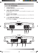
2.2 FRONT PANEL EA480
1 POWER LED
Green „operation“ LED, signaling correct operation of the amplifier.
2 INPUT GAIN CONTROL 1/2-CH
Input level control for 1/2-CH amplifier section - allowing to match the output voltage of
the head-unit‘s RCA line-outs to the amplifier input section.
3 HIGH PASS FREQUENCY CONTROL 1/2-CH
Control for the frequency adjustment of the 12dB/oct. high-pass filtering of the speakers
connected to 1/2-CH output terminals.
4 OPERATION MODE SWITCH 1/2-CH
Switch to select the operation mode of the crossover filter driving 1/2-CH section of the
amplifier.
5 LOW PASS FREQUENCY CONTROL 1/2-CH
Control for the frequency adjustment of the 24dB/oct. low-pass filtering of the speakers
connected to 1/2-CH output terminals.
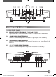
6 INPUT GAIN CONTROL 3/4-CH
Input level control for 3/4-CH amplifier section - allowing to match the output voltage of
the head-unit‘s RCA line-outs to the amplifier input section.
7 HIGH PASS FREQUENCY CONTROL 3/4-CH
Control for the frequency adjustment of the 12dB/oct. high-pass filtering of the speakers
connected to 3/4-CH output terminals.
8 OPERATION MODE SWITCH 3/4-CH
Switch to select the operation mode of the active crossover driving 3/4-CH section of the
amplifier.
9 LOW PASS FREQUENCY CONTROL 3/4-CH
Control for the frequency adjustment of the 24dB/oct. low-pass filtering of the speakers
connected to 3/4-CH output terminals.
10 PROTECTION LED
Red „protection“ LED, signaling faulty speaker connections or general malfunction of the
amplifier.
11 RCA INPUTS 1/2-CH 3/4-CH
Low-level stereo RCA signal input for connection with head-unit.
EA 2-4-5 CH Manual (EDF).indd 8 01.03.2006 9:30:11 Uhr