EMPIRE INSTALLATION INSTRUCTIONS AND OWNER'S MANUAL Comfort Systems Vent-Free Gas Fireplaces unVented GAS Fireplace ModELS VFP32BP(20,21)L(N,P)-1 VFP32BP(30,31)L(N,P)-1 VFP36BP(20,21)L(N,P)-1 VFP36BP(30,31)L(N,P)-1 Installer: Leave this manual with the appliance. Consumer: Retain this manual for future reference. WARNING: If the information in these instructions are not followed exactly, a fire or explosion may result causing property damage, personal injury or loss of life.
TABLE OF CONTENTS SECTION PAGE Important Safety Information.................................................................................... 3 Safety Information for Users of LP Gas................................................................... 4 Introduction.............................................................................................................. 5 Specifications...........................................................................................................
IMPORTANT SAFETY INFORMATION • • • • • • • • • • An unvented room heater having an input rating of more than 6,000 Btu per hour shall not be installed in a bathroom An unvented room heater having an input rating of more than 10,000 Btu per hour shall not be installed in a bedroom or bathroom. Due to high temperatures, the appliance should be located out of traffic and away from furniture and draperies.
SAFETY INFORMATION FOR USERS OF LP-GAS Propane (LP-Gas) is a flammable gas which can cause fires and explosions. In its natural state, propane is odorless and colorless. You may not know all the following safety precautions which can protect both you and your family from an accident. Read them carefully now, then review them point by point with the members of your household. Someday when there may not be a minute to lose, everyone's safety will depend on knowing exactly what to do.
INTRODUCTION Instructions to Installer 1. Installer must leave instruction manual with owner after installation. 2. Installer must have owner fill out and mail warranty card supplied with unvented room heater. 3. Installer should show owner how to start and operate unvented room heater. Always consult your local Building Department regarding regulations, codes or ordinances which apply to the installation of an unvented room heater.
SPECIFICATIONS Model VFP32BP VFP36BP Input Maximum 32,000 36,000 Minimum 22,000 25,000 Height without standoff 32 3/4" 34 3/4" Width 34” 39” Depth 17 3/8" 17 3/8” Gas Inlet 3/8” 3/8” Minimum Firebox Opening Accessories EK-1 Embers Kit PE-20 Platinum Embers FBB4* Variable Speed Automatic Blower VPP32A VFP32BP — Ceramic Aged Brick Liner VPP36A VFP36BP — Ceramic Aged Brick Liner Accessories For VFP(32,36)BP(30,31) Only FRBC Battery Operated Remote Control FRBTC Battery Operat
WATER VAPOR: A BY-PRODUCT OF UNVENTED ROOM HEATERS Water vapor is a by-product of gas combustion. An unvented room heater produces approximately one (1) ounce (30ml) of water for every 1,000 BTU's (.3KW's) of gas input per hour. Unvented room heaters are recommended as supplemental heat (a room) rather than a primary heat source (an entire house). In most supplemental heat applications, the water vapor does not create a problem.
PROVISIONS FOR ADEQUATE COMBUSTION & VENTILATION AIR (continued) The space in the above example is a confined space because the actual BTU/Hr used is more than the maximum BTU/HR the space can support. You must provide additional fresh air. Your options are as follows: A. Rework worksheet, adding the space of an adjoining room. If the extra space provides an unconfined space, remove door to adjoining room or add ventilation grills between rooms. See Ventilation Air From Inside Building. B.
GAS SUPPLY Check all local codes for requirements, especially for the size and type of gas supply line required. Recommended Gas Pipe Diameter Pipe Length Schedule 40 Pipe Inside Diameter Tubing, Type L Outside Diameter Nat. L.P. Nat. L.P. 0-10 feet 0-3 meters 1/2” 12.7mm 3/8” 9.5mm 1/2” 12.7mm 3/8” 9.5mm 10-40 feet 4-12 meters 1/2” 12.7mm 1/2” 12.7mm 5/8” 15.9mm 1/2” 12.7mm 40-100 feet 13-30 meters 1/2” 12.7mm 1/2” 12.7mm 3/4” 19mm 1/2” 12.
GAS SUPPLY (continued) Checking Manifold Pressure VFP(32,36)BP(30,31)LN (Natural gas) will have a manifold pressure of approximately 3.5" w.c. (.871kPa) for maximum input or 1.7" w.c. (.423kPa) for minimum input at the pressure regulator outlet with the inlet pressure to the pressure regulator from a minimum of 4.5" w.c. (1.120kPa) for the purpose of input adjustment to a maximum of 10.5" w.c. (2.614kPa). VFP(32,36)BP(20,21)LN (Natural gas) will have a manifold pressure of approximately 6.0" w.c. (1.
COMBUSTIBLE MATERIALS Do not attach combustible material to the mantel of your fireplace. This is a fire hazard. No greeting cards, stockings or ornamentation of any type should be placed on or attached to the fireplace. This is a heating appliance. The flow of heat can ignite combustibles.
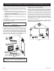
FIREPLACE DIMENSIONS H B C A I STANDOFF G J E D GAS LINE OPENING JUNCTION BOX ASSEMBLY GAS LINE OPENING Figure 8 Page 12 VFP32BP VFP36BP A 34" 39" B 29" 34" C 17 3/8" 17 3/8" D 31" 36" E 22 7/8" 24 7/8" F 32 3/4" 34 3/4" G 31 7/8" 34 3/8" H 45 1/8" 48 5/8" I 63 3/4" 68 3/4" J 35 3/4" 37 3/4" 28191-3-0611
INSTALLING HOOD AND TRIM KIT A black hood and trim kit is furnished with each model VFP(32,36)BP fireplace. The hood MUST be installed before the fireplace is used. Failure to do so may create a possible fire hazard. Attention: The hood is located behind top louver during shipment of fireplace. Remove top louver for access to hood. The trim kit is used to finish the fireplace. The trim kit is used in place of brick, marble or other finishing material. 1. To remove top louver, lift louver and pull forward.
FIREPLACE FRAMING AND INSTALLATION Fireplace framing can be built before or after the fireplace is set in place. Framing should be positioned to accommodate wall covering and fireplace facing material. The fireplace framing should be constructed of 2 x 4 lumber or heavier. 1. Place fireplace in framing opening. 2. Using the four (4) nailing flanges provided with the fireplace, attach two (2) flanges on each side. Attach flanges through prepunched holes.
PLACEMENT OF GLOWING EMBERS AND LAVA ROCK Placement of the glowing embers (rock wool) is very individual and light coverage of the areas indicated will provide your best effects. We recommend separation of the rock wool by hand and make your coverage as light and fluffy as possible. Place just enough embers on the burner to obtain the glow and a gold yellow flame. Do not place embers (rock wool) over large ports in rear portion of burner.
OPERATION INSTRUCTIONS/FLAME APPEARANCE Flames from the pilot (rear right back side of the pan burner) as well as the main flame should be visually checked as the log set is installed. In normal operation at full rate after 10 to 15 minutes, the flame appearance should be sets of yellow flames. NOTE: All flames will be random by design, flame height will go up and down. Glowing embers (rock wool) can cover the pan burner in between the front and middle logs, but very little is necessary to cover this area.
VFP(32,36)BP(30,31) lighting instructions FOR YOUR SAFETY READ BEFORE LIGHTING Warning: If you do not follow these instructions exactly, a fire or explosion may result causing property damage, personal injury or loss of life. A. This appliance has a pilot which must be lighted by hand. When lighting the pilot, follow these instructions exactly. B. Before lighting smell all around the appliance area for gas.
VFP(32,36)BP(20,21) lighting instructions FOR YOUR SAFETY READ BEFORE LIGHTING Warning: If you do not follow these instructions exactly, a fire or explosion may result causing property damage, personal injury or loss of life. A. This appliance has a pilot which must be lighted by hand. When lighting the pilot, follow these instructions exactly. B. Before lighting smell all around the appliance area for gas.
PILOT FLAME CHARACTERISTICS Figures 13 and 15 show a correct pilot flame pattern. The correct flame will be blue and will extend beyond the thermocouple. The flame will surround the thermocouple just below the tip. A slight yellow flame may occur where the pilot flame and main burner flame meet. Figures 14 and 16 show an incorrect pilot flame pattern. The incorrect pilot flame is not touching the thermocouple. This will cause the thermocouple to cool. When the thermocouple cools, the heater will shut down.
Cleaning and Pilot Maintenance Oxygen Depletion Sensor Pilot (Figure 17) When the pilot has a large yellow tip flame, clean the Oxygen Depletion Sensor as follows: 1. Clean the ODS pilot by loosening nut B from the pilot tubing. When this procedure is required, grasp nut A with an open end wrench. 2. Blow air pressure through the holes indicated by the arrows. This will blow out foreign materials such as dust, lint and spider webs. Tighten nut B also by grasping nut A.
TROUBLESHOOTING SYMPTOMS - POSSIBLE CAUSES AND CORRECTIONS Turn appliance OFF and allow to cool before servicing. Only a qualified service person should service and repair the heater. 1. When ignitor button is pressed, there is no spark at ODS/pilot. a. Ignitor electrode positioned wrong - Replace pilot. b. Ignitor electrode is broken - Replace pilot. c. Ignitor electrode not connected to ignitor cable Reconnect ignitor cable. d. Ignitor cable pinched or wet.
PARTS LIST Attention: When ordering parts, it is very important that part number and description of part coincide.
PARTS VIEW 1 2 3 6 7 8 9 4 5 11 16b 13 17 13 18 14 15 19 31 23b 21 22 29 25 31 20a 21 30 26a HYDRAULIC BURNER ASSEMBLY 28191-3-0611 17 18 14 15 19 26b 20b 10 16a 22 12 23a 24 25 MILLIVOLT BURNER ASSEMBLY 27 28 Page 23
OPTIONAL VARIABLE SPEED BLOWER INSTALLATION INSTRUCTIONS FBB4 Blower Installation Attention: Install blower assembly before connecting gas inlet supply line. Note: Junction box on right side of fireplace must be prewired at time of fireplace installation for use with blower assembly. It is recommended that an ON/OFF wall switch be installed that will activate the power supply to the furnace by a qualified electrician. See page 26 for junction box wiring instructions 1.
OPTIONAL VARIABLE SPEED BLOWER INSTALLATION INSTRUCTIONS (continued) Wiring The appliance, when installed, must be electrically grounded in accordance with local codes or, in the absence of local codes, with the National Electrical Code, ANSI/NFPA 70, if an external electrical source is utilized. This appliance is equipped with a three-prong [grounding] plug for your protection against shock hazard and should be plugged directly into a properly grounded three-prong receptacle.
JUNCTION BOX WIRING INSTALLATION INSTRUCTIONS CAUTION: ALL WIRING SHOULD BE DONE BY A QUALIFIED ELECTRICIAN AND SHALL BE IN COMPLIANCE WITH ALL LOCAL, CITY AND STATE BUILDING CODES. BEFORE MAKING THE ELECTRICAL CONNECTION, MAKE SURE THAT MAIN POWER SUPPLY IS DISCONNECTED. THE APPLIANCE, WHEN INSTALLED, MUST BE ELECTRICALLY GROUNDED IN ACCORDANCE WITH LOCAL CODES OR, IN THE ABSENCE OF LOCAL CODES, WITH THE NATIONAL ELECTRICAL CODE ANSI/NFPA 70 (LATEST EDITION).
MASTER PARTS DISTRIBUTOR LIST To Order Parts Under Warranty, please contact your local Empire dealer. See the dealer locator at www.empirecomfort. com. To provide warranty service, your dealer will need your name and address, purchase date and serial number, and the nature of the problem with the unit. To Order Parts After the Warranty Period, please contact your dealer or one of the Master Parts Distributors listed below. This list changes from time to time.
EMPIRE Comfort Systems Empire Comfort Systems Inc. 918 Freeburg Ave. Belleville, IL 62220 If you have a general question about our products, please e-mail us at info@empirecomfort.com. If you have a service or repair question, please contact your dealer. www.empirecomfort.