
Owner`s manual

29898-8-1114Page 22
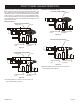
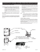
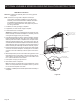
PILOT FLAME CHARACTERISTICS
INTERMITTENT PILOT
CorrectPilotFlamePattern
PILOT
SENSOR
IGNITOR
Figure 17
IncorrectPilotFlamePattern
PILOT
SENSOR
IGNITOR
Figure18
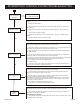
If pilot ame pattern is incorrect, as shown in Figure 18:
• See Troubleshooting, page 27-29.
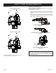
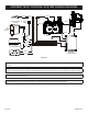
CleaningandPilotMaintenance
OxygenDepletionSensorPilot
When the pilot has a large yellow tip ame, clean the Oxygen
Depletion Sensor as follows:
1. Clean the ODS pilot by loosening nut B from the pilot tubing.
When this procedure is required, grasp nut A with an open end
wrench.
2. Blow air pressure through the holes indicated by the arrows.
This will blow out foreign materials such as dust, lint and spider
webs. Tighten nut B also by grasping nut A.
A
B
VFP(32,36)BP(30,31)MillivoltPilot
Figure 19
B
A
VFP(32,36)BP(20,21) HydraulicThermostatPilot
Figure 20
AB
VFP(32,36)BP(70,71) IntermittantPilot
Figure 21
Warning:
Neveruseneedles,wires,orsimilarcylindricalobjectsto
cleanthepilottoavoiddamagingthecalibratedrubythat
controlsthegasow.