
Owner`s manual

29898-8-1114 Page 25
INTERMITTENT CONTROL SYSTEM OPERATING INSTRUCTIONS
5.25VDCELECTRONICCONTROLVALVE
The electronic control valve system includes the ability to switch
the pilot from a standing pilot mode to an intermittent pilot mode.
• IPIMode - In the Intermittent Pilot mode, when the unit is
turned ON, it will cause spark to the pilot, light the pilot,
then allow the burner to light. When the unit is turned to
OFF, both the burner and pilot will be OFF.
• CPI Mode - In the Continuous Pilot mode, the pilot re-
mains ON continuously even when the burner is turned
OFF.
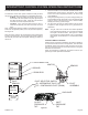
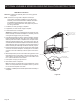
Note: A small toggle switch is located on a bracket that is used to
switch from IPI (upward position) to the CPI (downward position).
See Figure 23.
When the unit is turned to ON, the electrical current will energize
a spark to the pilot igniter. Once the pilot sensor heats up (after a
few seconds), the valve will be energized, allowing gas to ow to
the burner.
1. Follow the SAFETY and LIGHTING INSTRUCTIONS for In-
termittent Pilot controls found in this manual, and on labels
found in the control compartment located in the lower cavity
of the appliance.
2. During the operating season (or in power outage periods), it is
recommended that the pilot remain in the CPI (standing pilot
mode) to reduce cold start issues, and/or conserve battery
backup power during a power outage.
3. The gas valve has inlet and outlet pressure taps as shown
in Figure 23. Refer to pages 10 and 11 for gas pressure re-
quirements.
Note: The gas control has a manual HI/LO ame adjustment
knob (regulator) that allows you to increase or decrease
the height of the burner ame. See Figure 23. Rotate
the HI/LO knob counterclockwise to “HI” to increase the
ame height, and clockwise to “LO” to decrease the ame
height.
OPTIONAL REMOTE CONTROLS
Optional remote controls are available for use with this appliance.
To connect the remote receiver to the appliance, rst disconnect
the ON/OFF switch wires from the white and green wire connec-
tors and connect the wires from the remote receiver to the green
and white wire connectors.
Follow the instructions included with the remote control for pro-
gramming and other operational information.
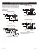
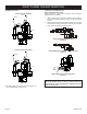
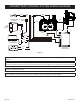
Figure 23
DFC
ELECTRONIC
CONTROL
MODULE
REMOTE
CONTROL
RECEIVER
AA (4)
BATTERY
BACKUP
IPI
CPI
PILOT SELECTOR SWITCH
IPI - INTERMITANT PILOT (UP)
CPI - CONTINUOUS PILOT (DOWN)
SPARK ROD
GROUND
9 PIN CONNECTOR
PILOT
SENSOR
GAS VALVE
OUTLET
PRESSURE
TAP
INLET
PRESSURE
TAP
IGNITOR
SENSOR
PILOT
ASSEMBLY