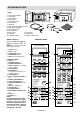
SERVICE MANUAL S0601R963EW// MICROWAVE OVEN WITH GRILL AND CONVECTION Jet Convection & 10 min Grill 1 min. 10sec. COOK ROAST BEEF / LAMB ROAST PORK ROAST POULTRY DEFROST CHICKEN PORTIONS STEAK / CHOPS CHILLED READY MEALS MINCED MEAT FRESH READY MEALS FRESH FISH CANNED FOOD RICE / PASTA FRESH VEG. 1 Oven Ready 2 Crispy CrumbPizza Foods 3 Baked Potatoes 4 Oven Chips 5 Yorkshire Pudding 6 Cake Kg.Lb.Pc s DOWN UP MICRO. POWER KITCHE N TIMER STOP CLEAR AUTO COOK Time LESS GRILL CONV.
SERVICING WARNING TO SERVICE PERSONNEL Microwave ovens contain circuitry capable of producing very high voltage and current, contact with following parts will result in electrocution. High voltage capacitor, High voltage transformer, Magnetron, High voltage rectifier assembly, High voltage harness. REMEMBER TO CHECK 3D REMEMBER TO CHECK 4R 1) Disconnect the supply. 2) Door opened, and wedged open. 3) Discharge high voltage capacitor. 1) Reconnect all leads removed from components during testing.
SERVICE MANUAL MICROWAVE OVEN WITH GRILL AND CONVECTION PRODUCT SPECIFICATIONS R-953(SL)M/ R-953(W)M/ R-963(SL)M/ R-963(W)M GENERAL IMPORTANT INFORMATION GENERAL INFORMATION This Manual has been prepared to provide Sharp Corp. Service engineers with Operation and Service Information. It is recommended that service engineers carefully study the entire text of this manual, so they will be qualified to render satisfactory customer service.
PRODUCT DESCRIPTION SPECIFICATION ITEM DESCRIPTION Power Requirements 230 - 240 Volts / 50 Hertz / Single phase, 3 wire earthed Power Consumption Microwave cooking 1.55 kW Approx. 6.7 A Convection cooking 2.85 kW Approx. 11.9 A Grill cooking 2.85 kW Approx. 11.9 A Micro and Grill ...................... 2.95 kW Approx. 12.6 A Dual cooking Micro and Convection ........... 2.95 kW Approx. 12.
APPEARANCE VIEW 4 1 2 11 10 OVEN 12 1. Grill heating element 2. Oven lamp 3. Control panel 4. Shelf runners 9 5. Waveguide cover 8 7 6. Oven cavity 7. Coupling 8. Door seals and sealing surfaces 9. Door opening handle 10.Air-vent openings 11.Outer cabinet 15.Low Rack 12.Power cord 16.High Rack 13.Turntable 17.Square shelves (x2) 14.Turntable support Note for R-963M: When is highlighted in the display, press the INFO key to read a specific hint which may assist you.
OPERATION SEQUENCE OFF CONDITION Closing the door activates the monitored latch switch and the stop switch. IMPORTANT: When the oven door is closed, the contacts COM-NC of the monitor switch must be open. When the microwave oven is plugged in a wall outlet (230 - 240V / 50Hz), the line voltage is supplied to the noise filter. Figure O-1 on page 32 1. The control unit is not energized. The display shows nothing (Fig. O-1 (a)). 2. Open the door.
OPERATION SEQUENCE Note: The On/Off time ratio does not exactly correspond to the percentage of microwave power, because approx. 3 seconds are needed for heating up the magnetron filament. GRILL COOKING CONDITION TOP GRILL (Figure O-3a) In this condition the food is cooked by the grill heating element . Programme the desired cooking time by touching the TIME keys and touch the GRILL key once. When the START key is touched, the following operations occur: 1.
OPERATION SEQUENCE ON/OFF TIME RATIO In grill cooking, convection cooking or dual cooking, the grill heating elements or magnetron operate within a 48 second time base. The following table is the ON / OFF time ratio at each power output of the grill heating element or magnetron. POWER OUTPUT 100% 90% 80% 70% 60% 50% 40% 30% 20% 10% ON TIME 48 sec. 44 sec. 40 sec. 36 sec. 32 sec. 26 sec. 22 sec. 16 sec. 12 sec. 8 sec. OFF TIME 0 sec. 4 sec. 8 sec. 12 sec. 16 sec. 22 sec. 26 sec. 32 sec. 36 sec. 40 sec.
OPERATION SEQUENCE AH SENSOR COOKING SEQUENCE 1. When the AH sensor cooking condition is started, the coil of shut-off relays (RY1+RY6) are energized, the oven lamp and cooling fan motor are turned on, but the power transformer is not turned on. NOTE: The oven should not be operated on AH SENSOR COOKING immediately after plugging in the unit. Wait two minutes before cooking on AH SENSOR COOKING CONDITION. 2. After about 16 seconds, the cook relay (RY2) is energized.
FUNCTION OF IMPORTANT COMPONENTS DOOR OPEN MECHANISM The door can be opened by pushing the open button on the control panel. When the open button is pushed, the open lever is pushes lower latch head on the door upward. The upper latch head is linked with the lower latch head, so now, the door can be opened. CAUTION: BEFORE REPLACING A BLOWN FUSE F8A, TEST THE MONITORED LATCH SWITCH AND MONITOR SWITCH FOR PROPER OPERATION. (REFER TO CHAPTER “TEST PROCEDURE”).
FUNCTION OF IMPORTANT COMPONENTS D2 D1 ASYMMETRIC RECTIFIER HIGH VOLTAGE RECTIFIER The rated peak reverse voltage of D1 of the asymmetric rectifier is 6 KV. The rated peak reverse voltage of D2 of the asymmetric rectifier is 1.7 KV. D1 and D2 of the asymmetric rectifier or high voltage rectifier are shorted when the each peak reverse voltage goes beyond the each rated peak reverse voltage. (The process of the blowing the fuse F8A.) 1.
FUNCTION OF IMPORTANT COMPONENTS 1. If the temperature of the thermistor does not rise to more than 40˚C after 4 minutes and 15 seconds from when the oven is started in convection, grill (top and bottom grills) or dual cooking mode, the oven is turned off. 2. When the thermistor or the wire harness to the thermistor is opened, the oven is turned off after 4 minutes and 15 seconds because this condition is same as above.
CONDITION OFF CONDITION R-953/963M - 11 COOKING CONDITION (COMMON MODE) MICROWAVE COOKING CONDITION CONVECTION COOKING CONDITION GRILL COOKING CONDITION DUAL COOKING CONDITION (COMMON MODE) DUAL COOKING CONDITION (MICRO./CONV.) DUAL COOKING CONDITION (MICRO./GRILL) SENSOR COOKING CONDITION PROBLEM Fuse F8A blows when the door is opened. Home fuse blows when power cord is plugged into wall outlet. Fuse 20A blows when power cord is plugged into wall outlet.
TEST PROCEDURES PROCEDURE LETTER A COMPONENT TEST MAGNETRON OUTPUT POWER TEST The power output of this oven is rated using the method specified by IEC 60705. Full details of how to curry out this procedure can be found in the Sharp Technical Training notes which is available from Sharp Parts Centre (part number SERV-LITMW01). The IEC60705 procedure must be carried out using laboratory-type procedures and equipment. These requirements make the procedure unsuitable for routine performance checks.
TEST PROCEDURES PROCEDURE LETTER C COMPONENT TEST HIGH VOLTAGE RECTIFIER TEST CARRY OUT 3D CHECKS. Isolate the high voltage rectifier assembly from the HV circuit. The high voltage rectifier can be tested using an ohmmeter set to its highest range. Connect the ohmmeter across the terminal B+C of the high voltage rectifier and note the reading obtained. Reverse the meter leads and note this second reading. The normal resistance is infinite in one direction and more than 100 kΩ in the other direction.
TEST PROCEDURES PROCEDURE LETTER F COMPONENT TEST THERMISTOR TEST CARRY OUT 3D CHECKS. Disconnect the connector B from CPU unit. Measure the resistance of the thermistor with an ohmmeter. Connect the ohmmeter leads to Pin No's C1 and C3 of the thermistor harness. Room Temperature 20˚C - 30˚C Resistance Approximately 359.9 kΩ - 152 kΩ If the meter does not indiicate above resistance, replace the thermistor. CARRY OUT 4R CHECKS. G THERMAL CUT-OUT TEST CARRY OUT 3D CHECKS.
TEST PROCEDURES PROCEDURE LETTER COMPONENT TEST L RED L 20A Cx N R1 L R2 Cy WHT F8A MEASURING POINTS Between N and L Between terminal N and WHITE Between terminal L and RED L (min) Cx ± 20% Cy ± 20% 1.0mH 0.22µF 4700pF INDICATION OF OHMMETER Approx. 680 kΩ Short circuit Short circuit If incorrect readings are absorbed, replace the noise filter unit. CARRY OUT 4R CHECKS. J BLOWN FUSE 20A CARRY OUT 3D CHECKS.
TEST PROCEDURES PROCEDURE LETTER M COMPONENT TEST TOUCH CONTROL PANEL ASSEMBLY TEST The touch control panel consists of circuits including semiconductors such as LSI, ICs, etc. Therefore, unlike conventional microwave ovens, proper maintenance can not be performed with only a voltmeter and ohmmeter.
TEST PROCEDURES PROCEDURE LETTER O COMPONENT TEST RELAY TEST CARRY OUT 3D CHECKS. Remove the outer case and check voltage between Pin Nos. 1 and 3 of the 4 pin connector (E) on the control unit with an A.C. voltmeter. The meter should indicate 230-240 volts, if not check oven circuit. Relay Test Check voltage at the relay coil with a D.C. voltmeter during the microwave cooking operation, grill operation, convection operation or dual operation. DC. voltage indicated .......... Defective relay. DC.
TEST PROCEDURES PROCEDURE LETTER Q COMPONENT TEST AH SENSOR TEST FOR R- 963(SL)M/(W)M Checking the initial sensor cooking condition (1) The oven should be plugged in at least two minutes before sensor cooking. (2) Room temperature should not exceed 35˚C. (3) The unit should not be installed in any area where heat and steam are generated. The unit should not be installed, for example, next to a conventional surface unit. Refer to the "INSTALLATION Instructions" .
TEST PROCEDURES Plunger 6-4. After approximately 3 seconds, the display shows "STAND COVER". If the above is not the case, the control unit is probably defective. If the above is proper, the AH sensor is probably defective. To connector (F) on Control Unit. 1 F-1 F-2 2 3 COM COM NO R1 F-3 CONNECTOR NC NO R2 R3 R4 NC R1,R2 : 22Ω ± 1% 1/2W R3 : 4.
DESCRIPTION OF LSI LSI(IXA034DR) The I/O signal of the LSI(IXA034DR) are detailed in the following table. Pin No. Signal I/O Description 1 1 AN0 AN0 IN IN Terminal not used. (For only R-953(SL)M/(W)M) Used for initial balancing of the bridge circuit (absolute humidity sensor). This input is an analog input terminal from the AH sensor circuit, and connected to the A/D converter built into the LSI.
DESCRIPTION OF LSI LSI(IXA034DR) The I/O signal of the LSI(IXA034DR) are detailed in the following table. Pin No. 22 23 Signal I/O Description INT1 INT0 OUT IN Terminal not used. Signal to synchronized LSI with commercial power source frequency(50Hz). This is basic timing for time processing H : GND of LSI. L (-5V) 20 msec. 24 25 CNVSS RESET IN IN Connected to VC. Auto clear terminal. Signal is input to reset the LSI to the initial state when power is applied.
DESCRIPTION OF LSI LSI(IXA034DR) The I/O signal of the LSI(IXA034DR) are detailed in the following table. Pin No. Signal I/O Description 36 P22 OUT Terminal not used. 37 P21 OUT Damper motor relay driving signal. To turn on and off shut-off relay (RY8). OFF ON H. GND L 38 P20 OUT Touch control transformer driving signal. To turn on and off the shut off relay (RY5). If the oven has not been used for more than 2 minutes, the relay RY5 will be turned off.
ABSOLUTE HUMIDITY SENSOR CIRCUIT 300k 14 R100 150k 15 R101 75k 16 R102 37.4k 17 C. Thermistor in closed vessel S. Thermistor in open vessel R97 47k F-1 C R96 F-3 3.57k C90 Absolute humidity (g/m 2 ) S R-953/963M - 23 F-2 R91 3.32k R92 1.
SERVICING 1. Precautions for Handling Electronic Components This unit uses CMOS LSI in the integral part of the circuits. When handling these parts, the following precautions should be strictly followed. CMOS LSI have extremely high impedance at its input and output terminals. For this reason, it is easily influenced by the surrounding high voltage power source, static electricity charge in clothes, etc., and sometimes it is not fully protected by the built-in protection circuit.
COMPONENT REPLACEMENT AND ADJUSTMENT PROCEDURE WARNING: Avoid possible exposure to microwave energy. Please follow the instructions below before operating the oven. 1. Disconnect oven from power supply. 2. Visually check the door and cavity face plate for damage (dents, cracks, signs of arcing etc.). Carry out any remedial work that is necessary before operating the oven. Do not operate the oven if any of the following conditions exist; 1. Door does not close firmly. 2.
COMPONENT REPLACEMENT AND ADJUSTMENT PROCEDURE 7. Disconnect the high voltage rectifier assembly from the high voltage capacitor. 8. Now, the high voltage rectifier assembly and the high voltage capacitor should be free. CAUTION: WHEN REPLACING HIGH VOLTAGE RECTIFIER ASSEMBLY, ENSURE THAT THE CATHODE (EARTH) CONNECTION IS SECURELY FIXED TO THE BASE PLATE THROUGH THE CAPACITOR HOLDER WITH AN EARTHING SCREW. HIGH VOLTAGE TRANSFORMER REMOVAL 1. CARRY OUT 3D CHECKS. 2.
COMPONENT REPLACEMENT AND ADJUSTMENT PROCEDURE CAUTION: • Do not hit the fan blade when installing because the bracket may be deformed. • Make sure that the fan blade rotates smoothly after installation. • Make sure that the axis of the shaft is not slanted. Coil 3. Insert the tabs of the fan duct to the back plate. 4. Install the fan duct to the back plate with the one (1) screw. 5. Re-install the chassis support to the oven cavity with the four (4) screws. 6.
COMPONENT REPLACEMENT AND ADJUSTMENT PROCEDURE CONVECTION HEATING ELEMENT REMOVAL 15.Remove the two (2) screws holding the convection heating element to the convection duct. 16.Remove the one (1) screw holding the convection heater angle to the convection duct. 17. Remove the one (1) screw holding the convection heater angle and the air separate angle D to the convection duct. 18. Remove the one (1) screw holding the convection heater angle A to the convection duct. 19.
COMPONENT REPLACEMENT AND ADJUSTMENT PROCEDURE GRILL HEATING ELEMENTS REMOVAL 1. CARRY OUT 3D CHECKS. 2. Disconnect wire leads from the thermal cut-out (GRILL). 3. Remove the two (2) screws holding the AH sensor assembly to the exhaust duct and remove the AH sensor assembly (only for R-963M) 4. Remove the two (2)screws holding the two (2) terminals of the main wire harness to the two (2) grill heating elements. 5. Remove the one (1) screw holding the exhaust duct to the oven cavity top plate. 6.
COMPONENT REPLACEMENT AND ADJUSTMENT PROCEDURE DOOR REPLACEMENT REMOVAL 1. 2. 3. 4. 5. 6. Disconnect the oven from the power supply. Push the door slightly. Remove the door stopper from the choke cover. Lift the door upwards. Now, door assembly is free from oven cavity. Insert an putty knife (thickness of about 0.5mm) into the gap between the choke cover and door frame as shown in Figure C-7 to free engaging parts. 7. Release choke cover from door panel. 8. Now choke cover is free.
MICROWAVE MEASUREMENT After any repair, the microwave oven must be checked for microwave leakage to ensure continued safe operation. BS EN 60335-2-25 specifies that the maximum permitted leakage with a load of 275 ml is 50 W/m2 (equivalent to 5 mW/cm2) at a distance of 5 cm from the oven. PREPARATION The following items are required to carry out this test:1. A low form of 600 ml beaker made from an electrically non-conductive material, such as glass or plastic, with an inside diameter of approximately 8.
GRILL THERMAL CUT-OUT N DAMPER THERMISTOR SWITCH RY5 R-953/963M - 32 MONITORED LATCH SWITCH RY6 STOP SWITCH COM. N.O . N.C. COM. MONITOR N.C. SWITCH N.O. Figure O-1(b) Oven Schematic-OFF Condition when the oven door is opened. ASYMMETRIC RECTIFIER H.V. RECTIFIER MAGNETRON HIGH VOLTAGE TRANSFORMER N.O. CAPACITOR 1.16 F AC2100V GRILL HEATING ELEMENTS COM. CONVECTION HEATING ELEMENT N.O . N.C. TTM RY8 TTM CM H.V. RECTIFIER CAPACITOR 1.
GRILL THERMAL CUT-OUT N DAMPER THERMISTOR SWITCH RY5 R-953/963M - 33 MONITORED LATCH SWITCH RY6 STOP SWITCH COM. N.O . N.C. TTM RY8 COM. Figure O-2 Oven Schematic-Microwave cooking Condition N.O. MONITOR N.C. SWITCH ASYMMETRIC RECTIFIER H.V. RECTIFIER MAGNETRON HIGH VOLTAGE TRANSFORMER N.O. CAPACITOR 1.16 F AC2100V GRILL HEATING ELEMENTS COM. CONVECTION HEATING ELEMENT N.O . N.C. TURNTABLE MOTOR COM.
DAMPER THERMISTOR SWITCH RY5 R-953/963M - 34 MONITORED LATCH SWITCH RY6 STOP SWITCH COM. N.O . N.C. COM. Figure O-4 Oven Schematic-Convection Condition MONITOR N.C. SWITCH N.O. ASYMMETRIC RECTIFIER H.V. RECTIFIER MAGNETRON HIGH VOLTAGE TRANSFORMER N.O. CAPACITOR 1.16 F AC2100V GRILL HEATING ELEMENTS COM. CONVECTION HEATING ELEMENT TURNTABLE MOTOR N.O . N.C. TTM RY8 FM COM. FAN MOTOR MONITORED LATCH SWITCH CM STOP SWITCH CONVECTION MOTOR RY6 TTM E1 H.V.
GRILL THERMAL CUT-OUT N DAMPER THERMISTOR SWITCH RY5 R-953/963M - 35 MONITORED LATCH SWITCH RY6 STOP SWITCH COM. N.O . N.C. COM. MONITOR N.C. SWITCH N.O. Figure O-5(b) Oven Schematic-Dual cooking Condition (Microwave and Grill) MAGNETRON N.O. ASYMMETRIC RECTIFIER H.V. RECTIFIER CAPACITOR 1.16 F AC2100V HIGH VOLTAGE TRANSFORMER COM. GRILL HEATING ELEMENTS CONVECTION HEATING ELEMENT N.O . N.C. TURNTABLE MOTOR TTM RY8 FM MONITORED LATCH SWITCH FAN MOTOR COM.
2 1 BLK AH SENSOR GRILL HEATING ELEMENT GRN CONTROL PANEL OVEN LAMP THERMAL CUT-OUT(GRILL) GRN 1 RED 2 GRN 3 BRN 4 BLU STOP SWITCH GRN NO COM 1 1 CN-1 WHT WHT WHT WHT WHT W H T G–Y B L K BRN BLU 5 15 CN-2 4 12 3 RED N L 2 1 CN-B 1 WH-1 15 R-953/963M - 36 1 CN-5 CN-C 5 YLW BLK N.C. YLW WHT RED RED WHT WHT WHT CONVECTION MOTOR RED BLK CONVECTION HEATING ELEMENT RY8 CN-E BLK F2 COM 1 RY1 RED NOISE FILTER WHT COM.
POWER UNIT CIRCUIT C1 C3 D10 S1NB10 – b (J1) E7 A3 – Q1 2SB1238 R5 3.3k WH1-3 GND WH1-6 VC WH1-9 BUZZER WH2-2 VA WH1-10 VR WH1-5 WH1-11 INT POWER CONTROL R3 680 1w c D5 SP1 A5 D6 RY6 FAN MOTOR OVEN THERMISTOR R4 510 1w RY5 (J2) AC230-240V 50Hz DOOR OPEN CONTACT A1 + WH1-4 C4 10µ/35v a + C3 C1 VRS1 10G471K d E5 R1 2.
(A) C2-4 Q21 DTA143EKA See Schm. Diag. C C2-3 (N) (D) Q23DTA143EKA C1-8 (E) C1-7 (M) (K) A0 A1 A2 GND (G) HIGH VOLTAGE TRANSFORMER C1-14 C100 C1-13 Q26 DTA123JKA IC4 AT24C01A (H) C1-1 C1-2 DAMPER SWITCH C2-1 OVEN THERMISTOR C1-4 Q27 DTA123JKA (K) D20 D21 Q28 DTA123JKA R31 15k D30 R56 1M CF1 CST4.00MGW NOTE : R85 15k R81 0Ω (P) R82 18kF (M) : IF NOT SPECIFIED 1/10W ± 5% : IF NOT SPECIFIED 1SS355 : IF NOT SPECIFIED 0.01µF/25V (R) R80 510kF R58 4.7k (Q) C83 R30 4.
Q30 DTA143EKA C52 (A) Q20 DTA143EKA IC2 BA4558F 5 (B) R92 1.8kF C2-3 8 4 R94 10k See Schm. Diag. C R97 47k R98 620k R99 300k (N) R100 150kF Q23DTA143EKA R101 75kF R102 37.4kF Q24 DTA143EKA HIGH VOLTAGE TRANSFORMER C1-14 C100 C1-13 C1-1 C1-2 Q27 DTA123JKA (K) D20 D21 Q28 DTA123JKA R31 15k D30 OVEN THERMISTOR (J16) F-3 R81 0Ω C1-4 C80 R82 18kF R85 15k (P) : IF NOT SPECIFIED 1/10W ± 5% : IF NOT SPECIFIED 1SS355 : IF NOT SPECIFIED 0.
GND IC1-55(P37) IC1-56(P36) IC1-57(P35) IC1-58(P34) IC1-59(P33) IC1-60(P32) IC1-61(P31) IC1-62(P30) IC1-63(P87) IC1-64(P86) D7 D6 D5 D4 D3 D2 D1 D0 INT MAIN IC1-66(P84) IC1-65(P85) IC1-54(P00) SUB IC1-53(P01) GND RESET VC VC R134 15k R128 4.7k C123 0.1µ/50v C122 0.1µ/50v C121 0.1µ/50v C120 0.1µ/50v 25 51 50 VDD NC NC RESET TEST VREF R03 R02 R01 R00 P13 P12 P11 P10 P03 P02 P01 P00 K03 K02 K01 K00 NC NC NC 26 IC3 IXA044DR Figure S-4. Indicator Circuit C125 0.
R69 15k IC1-7(P72) IC1-8(P71) IC1-46(P10) R60 15k IC1-45(P11) R61 15k IC1-44(P12) R62 15k IC1-43(P13) R63 15k IC1-42(P14) R64 15k IC1-41(P15) G4 G3 G2 G1 ROAST POULTRY ROAST PORK STEAK/ CHOPS CHICKEN PORTIONS ROAST BEEF/ LAMB 10 sec. 1 min. 10 min. MINCED MEAT AUTO COOK MORE LESS DUAL CONV.
ROAST PORK STEAK/ CHOPS CHICKEN PORTIONS MINCED MEAT CANNED FOOD FRESH VEG. MORE LESS FROZEN READY MEALS AUTO START CLOCK ROAST BEEF/ LAMB CHILLED READY MEALS START AUTO MINUTE RICE/ PASTA STOP CLEAR Kg / Lb DUAL CONV./ GRILL VC GND IC1-77(AN4) IC1-18(P47) IC1-22(INT1) Figure S-5(b).
PRINTED WIRING BOARD POWER UNIT DIP 1 15 1 4 1 CN - B WH1 WH2 1 4 D3 B D1 MICRO RY2 RY1 OL:TTM DAMP R3 B ZD1 D8 E Q1 R1 CN - D 1 D7 D6 7 C4 E R6 Q2 3 6 C3 ROTI 5 RY9 R4 1 CN - C 4 5 Q3 D2 8 3 SP1 R5 C5 E B R2 D9 ZD2 2 RY8 CF 1 D4 C2 RY3 TH RY7 C1 D5 D10 CH:BH RY4 9 (J1) CN - A 7 CN - E FM RY6 (J2) 1 VRS1 POWER CONT Figure S-6.
PARTS LIST Note: The parts marked "∆" may cause undue microwave exposure. / The parts marked "*" are used in voltage more than 250V. / "§" Mark: Spare parts delivery section REF. NO. PART NO.
PARTS LIST Note: The parts marked "∆" may cause undue microwave exposure. / The parts marked "*" are used in voltage more than 250V. / "§" Mark: Spare parts delivery section REF. NO. 333333333333- 5 5 6 7 7 7 7 8 8 8 8 9 PART NO.
PARTS LIST Note: The parts marked "∆" may cause undue microwave exposure. / The parts marked "*" are used in voltage more than 250V. / "§" Mark: Spare parts delivery section REF. NO. PART NO.
OVEN PARTS 2-2 7-16 4-17 7-10 1-17 4-25 7-5 6-11 4-20 4-18 4-45 7-13 1-9 7-17 7-13 4-27 1-25 4-10 4-22 7-16 7-3 These holes for R963M only 4-21 4-19 4-13 7-13 4-23 4-15 7-17 4-3 7-12 7-3 7-16 1-8 4-16 7-3 7-10 4-24 7-3 4-1 4-11 4-14 4-26 4-30 1-12 1-14 7-14 7-15 4-29 7-3 7-16 7-12 4-39 7-4 1-24 7-3 4-24 4-28 1-15 1-20 7-6 4-9 4-37 7-16 4-4 4-8 4-38 4-2 4-7 7-11 7-1 7-14 4-5 7-10 1-4 1-7 7-9 4-6 1-19 7-13 7-10 4-34 1-2 6-2 4-12 1-3 4-40 4-41 7-1 7
CONTROL PANEL / DOOR PARTS CONTROL PANEL PARTS 3-2 3-3 3-6 3-4 3-9 3-7 3-1 3-8 5-2 5-1 3-5 5-1-8 5-1-1 5-1-3 5-1-2 5-1-8 DOOR PARTS 5-1-5 5-1-7 5-1-6 5-1-4 R-953/963M - 48
MISCELLANEOUS / PACKING & ACCESSORIES MISCELLANEOUS 6-4 6-8 6-9 6-5 Actual wire harness may be different than illustration.
COPYRIGHT C 2000 BY SHARP CORPORATION ALL RIGHT RESERVED. No part of this publication may be reproduced, stored in a retrieval system, or transmitted in any form or by any means, electronic, mechanical, photocopying, recording, or otherwise, without prior written permission of the publisher. 2000 SHARP CORP. (6S1.31E) Printed in U.K.