INSTALLATION INSTRUCTIONS AND OWNER'S MANUAL CONTEMPORARY LINEAR VENT-FREE FIREPLACE VFLL48SP(3,9)0L(N,P)-1 Unvented GAS Fireplace ModELS VFLL48SP(3,9)0L(N,P)-1 VFLZ48SP(3,9)0L(N,P)-1 GAS-FIRED UL FILE NO. MH46389 VFLZ48SP(3,9)0L(N,P)-1 Installer: Consumer: Leave this manual with the appliance. Retain this manual for future reference. WARNING: If the information in these instructions are not followed exactly, a fire or explosion may result causing property damage, personal injury or loss of life.
TABLE OF CONTENTS SECTION PAGE IMPORTANT SAFETY INFORMATION................................................................................. 3 SAFETY INFORMATION FOR USERS OF LP-GAS............................................................ 4 IMPORTANT INSTALLATION GUIDELINES......................................................................... 5 INTRODUCTION................................................................................................................... 6 ACCESSORIES.................
IMPORTANT SAFETY INFORMATION DANGER: Indicates a hazardous situation which, if not avoided, will result in death or serious injury. WARNING: Indicates a hazardous situation which, if not avoided, could result in death or serious injury. • WARNING! This fireplace needs fresh air for ventilation to run properly. This fireplace has an ODS (oxygen depletion sensor) which will shut down the heater if adequate fresh air is not available. See troubleshooting section in the instructions.
SAFETY INFORMATION FOR USERS OF LP-GAS Propane (LP-Gas) is a flammable gas which can cause fires and explosions. In its natural state, propane is odorless and colorless. You may not know all the following safety precautions which can protect both you and your family from an accident. Read them carefully now, then review them point by point with the members of your household. Someday when there may not be a minute to lose, everyone’s safety will depend on knowing exactly what to do.
IMPORTANT INSTALLATION GUIDELINES Proper Primary Airflow into Burner For proper burner operation and flame appearance, the flow of primary air into the venturi tube, located on the rear of the burner, must not be reduced. This flow of air is reduced if dirt, lint or other obstructions build-up around or inside the venturi. Any obstruction in the venturi tube area must be removed.
INTRODUCTION Instructions to Installer 1. Installer must leave instruction manual with owner after installation. 2. Installer must have owner fill out and mail warranty card supplied with unvented room heater. 3. Installer should show owner how to start and operate unvented room heater. Always consult your local Building Department regarding regulations, codes or ordinances which apply to the installation of an unvented room heater.
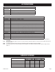
ACCESSORIES Accessories for VFL(L,Z)48SP30 (Millivolt) Models Remote Control Description Accessories FRBTC Battery Operated Remote Control with Thermostat FRBTP Battery Operated Programmable Remote Control TRW Remote Wall Thermostat (Wireless) OPTIONAL ACCESSORIES Part Number Description DF48WHP Decorative Front, Tidewater - Pewter DF48WBL Decorative Front, Tidewater - Black DF484BL Decorative Front, 4" Surround - Black DG1AB Decorative Glass Droplets - 1/2" Aqua Blue (One kit per one square
FIREPLACE DIMENSIONS When planning a fireplace insert installation, it’s necessary to determine: • Gas supply piping (left side entrance). • Electrical connections - for optional light kit • • Electrical supply requirements for optional light. (120V, 60Hz, 1 Amp) (right side entrance) Proper opening size of fireplace required for installation of the fireplace insert.
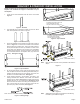
BRACKET & STANDOFF INSTALLATION NOTE: You must use the standoffs that are supplied with the fireplace. The standoffs are shipped in a flat-state on top of the fireplace. 1. Locate the six steel standoffs under the burner cover. See Figure 2. STANDOFF MOUNTING HOLES FOR NON-COMBUSTIBLE BOARD AROUND OUTSIDE OF FIREPLACE Figure 2 - Standoff 2. The standoffs have a perforation located on each end. Bend them at the perforation as shown in Figure 3.
JUNCTION BOX WIRING INSTALLATION CAUTION: ALL WIRING SHOULD BE DONE BY A QUALIFIED ELECTRICIAN AND SHALL BE IN COMPLIANCE WITH ALL LOCAL, CITY AND STATE BUILDING CODES. BEFORE MAKING THE ELECTRICAL CONNECTION, MAKE SURE THAT MAIN POWER SUPPLY IS DISCONNECTED. THE APPLIANCE, WHEN INSTALLED, MUST BE ELECTRICALLY GROUNDED IN ACCORDANCE WITH LOCAL CODES OR, IN THE ABSENCE OF LOCAL CODES, WITH THE NATIONAL ELECTRICAL CODE ANSI/NFPA 70 (LATEST EDITION). 2.
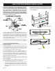
JUNCTION BOX WIRING INSTALLATION 3. Lift the complete burner and valve assembly upward, then turn it sideways in fireplace opening to gain easy access to the junction box. You may remove the complete burner and valve assembly as shown in Figure 12. Figure 14 (VFLL48SP shown) 5. Figure 12 4 The junction box is located on the end of the fireplace. Remove the 5/16” Hex screw that secures the junction box to the firebox, and remove the junction box. See Figure 13.
GAS SUPPLY The gas pipeline can be brought in through the right or left side of the appliance. The insert has a Flexline with shutoff valve located on the left side when facing the unit. See Figures 16 and 17. Consult the current National Fuel Gas Code, ANSI Z223.1 CAN/CGA-B149 (.1 or .2) installation code. Recommended Gas Pipe Diameter Pipe Length Schedule 40 Pipe Inside Diameter Tubing, Type L Outside Diameter Nat. L.P. Nat. L.P. 0-10ft 0-3m 1/2" 12.7mm 3/8" 9.5mm 1/2" 12.7mm 3/8" 9.
CLEARANCES Note: Combustible material is allowed below a fireplace viewing area opening and outside the non-combustible board indicated area. Note: To finish the wall using DF(38,48)4BL Decorative Front, stop finishing materials 2-7/8 inches above the fireplace upper opening and 2-3/8 inches below the lower opening. This will allow 3/8 inch space for lifting the front to unhook and remove it. The optional front will overlap the finish materials.
CLEARANCES DIMENSION (IN INCHES) MODEL A B C D E F VFL(L,Z)48 21 23 25 27 29 31 Figure 19 Television Considerations Installing a television above a fireplace has become increasingly popular; however, the area above any fireplace gets hot and most TV manufacturers recommend against placing their products near a heat source. If you install a television above this fireplace, Empire Comfort Systems accepts no responsibility for damage or injuries.
FIREPLACE INSTALLATION Wall Thermostat Considerations For optimal performance, the thermostat should be installed in the room with the appliance and the highest ceiling. Built-In Fireplace Installation Built-in installation of this fireplace involves installing the fireplace into a framed-in enclosure. This makes the front of the fireplace flush with a wall or the front of the fireplace window flush with a wall. Frame in rough opening. Use dimensions shown in Figure 21 for a conventional rough opening.
FIREPLACE INSTALLATION Rough Opening for Installing in Wall (Built-In) Figure 21 Rough Opening for Elevated Installation (Built-In) Figure 22 TABLE 1 - MINIMUM DIMENSIONS (in inches) FOR FIGURES 21 & 22 A B C D E F 12-13/16* 53 35-1/4 53-1/2 75-5/8 37-7/8 *Minimum clearance with 1/2-in. non-combustible board over both faces of fireplace. If non-combustible board is to top of fireplace, reduce depth by 1/2-in. for each side.
WATER VAPOR: A BY-PRODUCT OF UNVENTED ROOM HEATERS Water vapor is a by-product of gas combustion. An unvented room heater produces approximately one (1) ounce (30ml) of water for every 1,000 BTU's (.3KW's) of gas input per hour. Unvented room heaters are recommended as supplemental heat (a room) rather than a primary heat source (an entire house). In most supplemental heat applications, the water vapor does not create a problem.
PROVISIONS FOR ADEQUATE COMBUSTION & VENTILATION AIR (continued) The space in the above example is a confined space because the actual BTU/Hr used is more than the maximum BTU/HR the space can support. You must provide additional fresh air. Your options are as follows: A. Rework worksheet, adding the space of an adjoining room. If the extra space provides an unconfined space, remove door to adjoining room or add ventilation grills between rooms. See Ventilation Air From Inside Building. B.
COMBUSTIBLE MATERIALS Television Considerations Installing a television above a fireplace has become increasingly popular; however, the area above any fireplace gets hot and most TV manufacturers recommend against placing their products near a heat source. If you install a television above this fireplace, Empire Comfort Systems accepts no responsibility for damage or injuries. Follow the television manufacturer’s installation instructions, including any recommendations regarding proximity to heat sources.
CLEANING AND SERVICING Annual inspection and cleaning by your dealer or qualified service technician is recommended to prevent malfunction and/or sooting. 2. TURN OFF HEATER AND ALLOW TO COOL BEFORE CLEANING. Remove any optional decorative covers or decorative glass material. Gloves are recommended. Use canned air to blow through the holes indicated by the arrows. This will blow out foreign materials such as dust, lint and spider webs. Use a wrench to hold Nut A as you tighten Nut B.
DECORATIVE ACCESSORY INSTALLATION WARNING Failure to position the parts in accordance with the diagrams and instructions below or failure to use only parts specifically approved for use with this heater may result in property damage or personal injury. INSTALLATION 1. Remove glass front from fireplace by lifting the glass front up, sliding it to the right, and then carefully angle left side out of the slots. See Figures 30 - 32 (VFLL48SP shown).
DECORATIVE ACCESSORY INSTALLATION 2. Apply the accessory decorative glass or rocks to the shaded area only. Use enough to cover the floor of the fireplace, but do not allow the decorative glass or rocks to reach higher than the flange surrounding the burner. Never place decorative glass or media inside the flange surrounding the burner itself. This fireplace can use crushed glass, glass droplets (1/2 inch), glass drops (1 inch), or ceramic fiber rocks and pebbles.
MILLIVOLT CONTROL VALVE LIGHTING INSTRUCTIONS FOR YOUR SAFETY READ BEFORE LIGHTING Warning: If you do not follow these instructions exactly, a fire or explosion may result causing property damage, personal injury or loss of life. A. B. This appliance has a pilot which must be lighted by hand. When lighting the pilot, follow these instructions exactly. department. C. Use only your hand to push in or turn the gas control knob. Never use tools.
IP LIGHTING INSTRUCTIONS FOR YOUR SAFETY READ BEFORE LIGHTING Warning: If you do not follow these instructions exactly, a fire or explosion may result causing property damage, personal injury or loss of life. A. This appliance has a pilot which must be lighted by hand. When lighting the pilot, follow these instructions exactly. B. Before lighting smell all around the appliance area for gas. Be sure to smell next to the floor because some gas is heavier than air and will settle on the floor.
PILOT FLAME CHARACTERISTICS Figures 37 and 38 show a correct pilot flame pattern. The correct flame will be blue and will extend beyond the thermocouple. The flame will surround the thermocouple just below the tip. A slight yellow flame may occur where the pilot flame and main burner flame meet. Figures 39 and 40 show an incorrect pilot flame pattern. The incorrect pilot flame is not touching the thermocouple. This will cause the thermocouple to cool. When the thermocouple cools, the heater will shut down.
MILLIVOLT WIRING Label all wires prior to disconnection when servicing controls. Wiring errors can cause improper and dangerous operation. Verify proper operation after servicing. Millivolt thermopile is self powered, gas valve does not require 110 volts. Maximum length of 20 feet of 16 AWG to conductor wires is to be used with all optional switches. Check 750 Millivolt System Operation Millivolt system and all individual components may be checked with a millivolt meter 0-1000 MV range.
FRBC - MILLIVOLT CONTROL SYSTEM INSTALLATION AND OPERATING INSTRUCTIONS IF YOU CANNOT READ OR UNDERSTAND THESE INSTALLATION INSTRUCTIONS DO NOT ATTEMPT TO INSTALL OR OPERATE INTRODUCTION This remote control system was developed to provide safe, reliable, and user-friendly remote control system for gas heating appliances. The system can be operated manually from the transmitter. The system operates on one of 255 security codes that are programmed into the transmitter at the factory.
FRBC - MILLIVOLT CONTROL SYSTEM WIRING INSTRUCTIONS INSTALLATION WARNING This remote control system must be installed exactly as outlined in these instructions. Read all instructions completely before attempting installation. Follow instructions carefully during installation. Any modifications of the ECS remote control or any of its components will void the warrant and may be pose a fire hazard. Do not connect any gas valve or electronic module directly to 110-120VAC power.
FRBC - MILLIVOLT CONTROL SYSTEM GENERAL INFORMATION MATCHING SECURITY CODES Each transmitter can use one of 255 unique security codes. It may be necessary to program the remote receiver to LEARN the security code of the transmitter upon initial use, if batteries are replaced, or if a replacement transmitter is purchased from your dealer or the factory.
MILLIVOLT TROUBLESHOOTING SYMPTOMS, POSSIBLE CAUSES AND CORRECTIONS 1. When ignitor button is pressed, there is no spark at ODS/ pilot. a. Ignitor electrode positioned wrong - Replace pilot. b. Ignitor electrode is broken - Replace pilot. c. Ignitor electrode not connected to ignitor cable - Reconnect ignitor cable. d. Ignitor cable pinched or wet. Keep ignitor cable dry - Free ignitor cable if pinched by any metal or tubing. e. Broken ignitor cable - Replace ignitor cable. f.
PROFLAME - IP CONTROL SYSTEM Technical Data Remote Control Supply voltage 4.5 V (three 1.5 V AAA batteries) Ambient temperature ratings 0-50°C (32 - 122°F) Radio frequency 315 MHz TRANSMITTER (REMOTE CONTROL WITH LCD DISPLAY) The Proflame Transmitter uses a streamline design with a simple button layout and informative LCD display (Figure 46). The Transmitter is powered by 3 AAA type batteries.
PROFLAME - IP CONTROL SYSTEM RECEIVER The Proflame Receiver (Figures 48a and 48b) connects directly to the gas valve and stepper motor with a wiring harness. The Receiver is powered by 4 AA type batteries. The Receiver accepts commands via radio frequency from the Transmitter to operate the appliance in accordance with the particular Proflame system configuration. The Receiver three position slider switch can be set to one of three positions: ON (Manual Override), Remote (Remote control) or Off.
PROFLAME - IP CONTROL SYSTEM Turn on the Appliance Press the ON/OFF Button on the Transmitter. The Transmitter display will show all active Icons on the screen. At the same time the Receiver connects the thermopile to the gas valve millivolt coil and the appliance main burner turns on. A single “beep” from the Receiver will confirm reception of the command. Turn off the Appliance Press the ON/OFF Button on the Transmitter. The Transmitter LCD display will only show the room temperature and Icon (Figure 51).
PROFLAME - IP CONTROL SYSTEM ROOM THERMOSTAT ( Transmitter Operation) The Remote Control can operate as a room thermostat. The thermostat can be set to a desired temperature to control the comfort level in a room. To activate this function, press the Thermostat Button (Figure 46). The LCD display on the Transmitter will change to show that the room thermostat is “ON” and the set temperature is now displayed (Figures 56a and 56b).
PROFLAME - IP CONTROL SYSTEM BUTTON LOCK This function will lock the buttons to avoid unsupervised operation. To activate this function, press the MODE and the UP Arrow Button at the same time (Figure 59). To de-activate this function, press the MODE and the UP Arrow Button at the same time. Receiver The life span of the Receiver batteries depends on various factors: quality of the batteries used, the number of ignitions of the appliance, the number of changes to the room thermostat set point, etc.
IP OPERATING INSTRUCTIONS 5.25 VDC ELECTRONIC CONTROL VALVE 1. The electronic control valve system includes the ability to switch the pilot from a standing pilot mode to an intermittent pilot mode. • IP Mode - In the Intermittent Pilot mode, when the unit is turned ON, it will cause spark to the pilot, light the pilot, then allow the burner to light. When the unit is turned to OFF, both the burner and pilot will be OFF.
IP WIRING If any of the original wire as supplied with this unit must be replaced, it must be replaced with equivalent gauge and temperature rated wire. This appliance is only for use with the type of gas indicated on the rating plate and may be installed in an aftermarket, permanently located, manufactured (mobile) home where not prohibited by local codes. This appliance is not convertible for use with other gases.
IP TROUBLESHOOTING Brief Description of the Components The Digital Fireplace Control (DFC) is an automatic gas ignition system based on a single micro-controller core. This control manages all functions related to ignition, flame sensing and supervision for atmospheric applications. The DFC can be set to provide continuous or intermittent ignition control sequences and flame monitoring with safety shutdown in case of failure. The DFC is set up as a stand alone (AC powered system with battery back up.
IP TROUBLESHOOTING 1 If the DFC giving signal lock out: The board should be unlocked to reinitiate a pilot flame ignition (for the correct unlock sequence refer to the DFC Use and Installation Instructions). NO Is the DFC board in lock out? NO 1. Verify the electrical connections’ integrity and make sure they are in accordance with the relevant system wiring diagram. If necessary replace the wire harness. 2. Replace the DFC board. YES 1. Check the spark electrode positioning - adjust as necessary.
IP TROUBLESHOOTING 2 Main burner lights when the pilot only should light. 1. Replace DFC board. 2. Replace the gas valve. YES 1. Verify the pilot flame fully engulfs the tip of the sense electrode. If not replace the pilot assembly. NO 2. Replace the pilot assembly. 3. Carefully clean the electrical connections of the sense cable, and the DFC board sense cable connection. Pilot holds the flame?. NO 4. Replace the sense cable, or the cable-sense electrode assembly, or the pilot assembly. 5.
MASTER PARTS DISTRIBUTOR LIST To Order Parts Under Warranty, please contact your local Empire dealer. See the dealer locator at www.empirecomfort. com. To provide warranty service, your dealer will need your name and address, purchase date and serial number, and the nature of the problem with the unit. To Order Parts After the Warranty Period, please contact your dealer or one of the Master Parts Distributors listed below. This list changes from time to time.
VFLL48SP(3,9) EXPLODED VIEW Actual parts may vary from those shown.
VFL(L,Z)48SP(3,9) PARTS LIST INDEX NO. MV PART NO. (SP3) DESCRIPTION IP PART NO. (SP9) DESCRIPTION INDEX NO.
WARRANTY Empire Comfort Systems Inc. warranties this hearth product to be free from defects at the time of purchase and for the periods specified below. Hearth products must be installed by a qualified technician and must be maintained and operated safely, in accordance with the instructions in the owner’s manual. Empire will not warranty any Boulevard fireplace that is not installed by the selling dealer or that dealer’s direct contract agents.