
Owner`s manual


32925-3-0115Page 10
CAUTION: ALL WIRING SHOULD BE DONE BY A QUALIFIED
ELECTRICIAN AND SHALL BE IN COMPLIANCE WITH ALL
-
MAIN POWER SUPPLY IS DISCONNECTED. THE APPLIANCE,
WHEN INSTALLED, MUST BE ELECTRICALLY GROUNDED IN
ACCORDANCE WITH LOCAL CODES OR, IN THE ABSENCE
OF LOCAL CODES, WITH THE NATIONAL ELECTRICAL CODE
ANSI/NFPA 70 (LATEST EDITION).
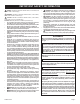
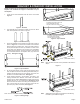
Figure 9
Afactoryinstalledjunctionboxislocatedatthelowerrightcorner
insidethereboxbottomcavity.Wiringmustbefedtothejunction
box through the outer wrap of the replace, then connected as
required inside thejunction box as directed above. Refer to the
instructionsabovetodeterminewhatwiringisneededdepending
on what valve system you have, and whether or not the optional
AccentLightkitwillbeinstalled.
Itisrecommendedthatapproximately6”ofwiringbeleftinthejunc-
tionboxtoallowforconnections.Forwiringdetail,refertoFigure 9.
Wiring
is only needed if adding the LK5 Accent Light accessory. Follow the
wiring instructions included with the LK5 to connect this optional
accessorythroughthejunctionboxtoawallswitch.
The
suggested 120V electrical requirements include installa-
tion of the electrical receptacle into the junction box lo-
cated at the lower right corner inside the rebox bottom cav-
ity.ThiswillbeusedtoplugintheAC/DCAdapterthatprovides
power to the electronic valve system.
Note: IfanLK5AccentLightkitistobeinstalled,aseparate120V
linewillbeneededtoconnectthelightkitwiringdirectlytoawall
switch. See Figure 9.
Itisrecommendedtomovethereplacetoitsnallocationornear
itbeforeinstallingelectricalwireorconnectinggaslines.
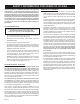
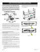
1. Toaccess and install the junction box and wiring, begin by
removingtheburnercover.Liftitstraightupoffoftheburner
and set aside. See Figure 10. For VFLL48SP90 Units: Remove
the heat shield and disconnect the wire to the switch on the
heat shield.
2. Removetheve5/16”Hexscrewsthatholddownthecomplete
burnerandvalveassembly.Therearethreescrewsonthefront
bottomange,andtwoonthebackbottomange,nearthe
ends. See Figure 11.
Figure 10
Figure 11
(VFLL48SP shown)
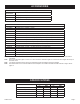
VFLL48SP(3,9)0L(N,P)-1
VFLZ48SP(3,9)0L(N,P)-1