
Owner`s manual


32925-3-0115 Page 9
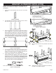
1. Locate the six steel standoffs under the burner cover. See
Figure 2.
Figure 2 - Standoff
2. The standoffs have a perforation located on each end. Bend
them at the perforation as shown in Figure 3.
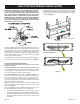
4. Securethestandoffstothereplacetopwitheightscrewsas
shown in Figure 4. The screws are located in the hardware
packetinsidetheenvelopepack.Thereareholeslocatedin
thetopofthereplaceforeachtopstandoff.Theholecloser
totheedgeofthereplaceisformountingnon-combustible
boardaroundtheopening.Theotherholesisformountingthe
non-combustible board to the replace face (top, sides and
bottom).See Figures 4 and 6.
5. Onthetopandbottomofeachsidearesideframingstand-
offs.Useplierstobendthesideframingstandoffsattheper-
forations90degreesawayfromthecabinet.Oncebent,this
willleavea1/2"standoffdimension. See Figure 7.
6. Locate framing brackets in the envelope. The holes in the
framing brackets allow different size boards and different
locationsfortheboards. See Figure 5. Install eight framing
bracketswithtwo10x1/2screws(each).See Figures 7 and
8.Usethefrontsetofholesifmountingaroundreplacewin-
dow. Usethe backset of holesif mountingaround the re-
placeface(top,sidesandbottom).See Figure 6.
Note:Thenon-combustibleboardprovidedis1/2"thick.
Figure 5 - Nailing Flange
STANDOFF MOUNTING HOLES FOR
NON-COMUSTIBLE BOARD
AROUND WINDOW OPENING
STANDOFF MOUNTING HOLES FOR
NON-COMBUSTIBLE BOARD
AROUND OUTSIDE OF FIREPLACE
Note: Bend the side standoffs at the perforations as stated in
Step 5.
Figure 7
Figure 8
Note: Additionalscrewsmadebeusedwiththesideframing
bracketstogiveadditionalsupport.
(VFLL48SP shown)
(VFLL48SP shown)