OWNER’S MANUAL AND INSTALLATION INSTRUCTIONS ULTRASAVER 90 PLUS WALL FURNACE MODELS PVS18(N,P)-1 PVS35(N,P)-1 Attention: Check local codes for venting requirements. Installer: Consumer: Leave this manual with the appliance. Retain this manual for future reference. WARNING: If the information in these instructions are not followed exactly, a fire or explosion may result causing property damage, personal injury or loss of life.
TABLE OF CONTENTS SECTION PAGE IMPORTANT SAFETY INFORMATION................................................................................ 3 SAFETY INFORMATION FOR USERS OF LP-GAS............................................................ 4 REQUIREMENTS FOR MASSACHUSETTS........................................................................ 5 GENERAL SAFETY INFORMATION.................................................................................... 6 OWNER’S MANUAL AND OPERATION INSTRUCTIONS.......
IMPORTANT SAFETY INFORMATION THIS IS A HEATING APPLIANCE Safety markings are frequently used in this manual to designate a degree or level of seriousness and should not be ignored. DANGER: Indicates a hazardous situation which, if not avoided, will result in death or serious injury. WARNING: Indicates a hazardous situation which, if not avoided, could result in death or serious injury. CAUTION: Indicates a hazardous situation which, if not avoided, could result in minor or moderate injury.
SAFETY INFORMATION FOR USERS OF LP-GAS Propane (LP-Gas) is a flammable gas which can cause fires and explosions. In its natural state, propane is odorless and colorless. You may not know all the following safety precautions which can protect both you and your family from an accident. Read them carefully now, then review them point by point with the members of your household. Someday when there may not be a minute to lose, everyone’s safety will depend on knowing exactly what to do.
REQUIREMENTS FOR MASSACHUSETTS For all side wall horizontally vented gas fueled equipment installed in every dwelling, building or structure used in whole or in part for residential purposes, including those owned or operated by the Commonwealth and where the side wall exhaust vent termination is less than seven feet above finished grade in the area of the venting, including but not limited to decks and porches, the following requirements shall be satisfied: 1. INSTALLATION OF CARBON MONOXIDE DETECTORS.
GENERAL SAFETY INFORMATION WARNING The safety information listed below must be followed during the installation, service, and operation of this product. Failure to following the safety recommendations could result in possible damage to the equipment, serious personal injury, or death. General Information This series is designed certified in accordance with American National Standard/CSA Standard Z21.86 and CSA IR 1.10 as a power vent wall furnace to be installed according to these instructions.
OWNER’S MANUAL AND OPERATION INSTRUCTIONS EMPIRE Comfort Systems www.empirezoneheat.
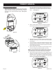
OWNER’S MANUAL Before You Start 2. 1. The shutoff valve should be in the “OPEN” position. See Figure 4. Verify there is electrical power to the wall furnace. Verify the main gas supply to the unit is on. Verify the Main Power Switch is turned on. See Figure 1. CLOSED OPEN Figure 4 Starting the Wall Furnace Figure 1 If electrical power is present, the red and green control board LED’s will begin to flash alternately. See Figure 3.
OWNER’S MANUAL 2. When the external control is activated, the wall furnace display panel will illuminate and show the heat level along with the remote signal symbol. The wall furnace will begin the start up sequence automatically. See Figure 6. Wall Furnace Operation - Local Mode (Internal Thermostat) 1. To operated the wall furnace in Local (thermostatic) mode, press the Mode Select button on the wall furnace display panel three times from the off mode.
OWNER’S MANUAL Wall Furnace Operations Sequence 1. Each light will pulse four times then the wall furnace will enter Remote mode. While in Remote mode, the green LED will flash slowly and the display panel will shown a double dash “- -”. See Figure 12. When the main power switch is turned on, the red and green control board LED’s will begin to flash alternately. If using the FRBTPL Remote accessory (page 15) the remote receiver will search for the remote transmitter’s signal. See Figures 10 and 11.
OWNER’S MANUAL 7. 8. The blower will activate after 45 to 70 seconds depending on heat level. The blower will automatically adjust its speed to match the heat level. The blower speed will be indicated on the display panel. See Figures 16 to 19. The heat level can be adjusted either up or down at any point during the wall furnace’s operation in Manual Mode. If using the Local mode, the wall furnace adjusts the level automatically.
OWNER’S MANUAL Humidifier Operation Remote Mode - Anti-tamper With the optional humidification tray kit (page 15), as the wall furnace operates condensate is collected and transferred to a pan in the bottom of the wall furnace. When the condensate reaches a certain level, a heating element evaporates the water into the air stream. To lock the display panel when operating the wall furnace in remote mode, press and hold the Mode, Up adjust and Down adjust buttons for ten seconds.
INSTALLATION INSTRUCTIONS EMPIRE Comfort Systems www.empirezoneheat.
INTRODUCTION FAQ - INSTALLATION CONSIDERATIONS What tools are needed for installation? Pipe Wrench Adjustable Wrench Drill Tape Measure 10” x 5/16” Nut Driver Thread Sealant Level 2-1/2” Diameter Hole Saw for 2” pipe 2” Diameter Hole Saw for 1-1/2” pipe 1” Diameter Hole Saw Non-corrosive Leak Check Solution Where will the wall furnace be installed? • On the Floor - Wall Furnace comes equipped from factory for this option. See Page 21. • Wall Mounted - Wall mount shroud needed. See Page 15 for kit number.
INTRODUCTION ACCESSORIES ACCESSORIES VENTING Part Number Description Typical Uses PVSA1 Air Pipe Kit Converts wall furnace from single flue to direct-vent PVSDV35A DV35 Vent Transition Cap Replaces DV35 Vent cap with a transition to PVC pipe for a 2” single flue.
INTRODUCTION SPECIFICATIONS AND DIMENSIONS SPECIFICATIONS Models PVS18(N,P) PVS35(N,P) Maximum Input BTU/HR (KW/H)* 17,500 (5.13) 35,000 (10.26) Minimum Input BTU/HR (KW/H)* 8,750 (2.56) 17,500 (5.13) Height 27-7/8” 27-7/8” Width 36-1/8” 36-1/8” 13 13 3/8” Pipe 3/8” Pipe Depth with Shroud** Gas Inlet (Pipe) Electrical - The wall furnace comes equipped with a 5 foot (1.
INTRODUCTION CLEARANCES TO COMBUSTIBLES Select a location with adequate accessibility clearances for servicing and proper installation. Locate the wall furnace within 5 feet of a 115 VAC wall receptacle to properly power the wall furnace. Do NOT use an extension cord.
INTRODUCTION WALL FURNACE DISPLAY Figure 24 Page 18 32084-6-0214
INTRODUCTION WALL FURNACE COMPONENT ARRANGEMENT - FRONT Figure 25 Figure 26 32084-6-0214 Page 19
INTRODUCTION WALL FURNACE COMPONENT ARRANGEMENT - REAR Figure 27 Figure 28 Page 20 32084-6-0214
WALL FURNACE INSTALLATION MOUNTING THE REAR SHROUD Tools Needed Pipe Wrench Adjustable Wrench Drill Tape Measure 10” x 5/16” Nut Driver Thread Sealant Level 2-1/2” Diameter Hole Saw for 2” pipe 2” Diameter Hole Saw for 1-1/2” pipe 1” Diameter Hole Saw Non-corrosive Leak Check Solution Move the wall furnace away from the wall and remove the rear shroud from the wall furnace. Remove four 10 x 1/2” hex-head screws and set aside. Determine if using a direct vent, single flue venting system.
WALL FURNACE INSTALLATION GAS SUPPLY All gas piping must be installed in compliance with local codes and utility regulations. In the absence of local codes the installation must comply with NFCG NFPA 54/ANSI Z223.1. Notice: Never use plastic pipe. Check to confirm whether your local codes allow copper tubing or galvanized. Where permitted, flexible gas connectors must be certified to the following standards: — ANS Z21.24 Appliance Connectors of Corrugated Metal Tubing and Fittings — ANS Z21.
WALL FURNACE INSTALLATION GAS SUPPLY Gas Supply Line to Wall furnace 1. Pull the factory installed flexible gas line through the hole in the back panel. See Figure 34. 2. Connect the gas supply line to flexible gas hose. Ensure that flexible gas hose is not kinked after fitting gas supply line. Any excess flexible line can be pushed back into the wall furnace. See Figure 34.
WALL FURNACE INSTALLATION VENT CLEARANCES US Installation 1 A= Clearance above any grade, veranda, porch or balcony 12 in (30 cm) B= Clearance to window or door that may be opened 6 in (15 cm) for appliances ≤ 10,000 Btu/h (3 kW), 9 in (23 cm) for appliances > 10,000 Btu/h (3 kW) and ≤ 50,000 Btu/h (15 kW), 12 in (30 cm) for appliances > 50,000 Btu/h (15 kW) C= Clearance to permanently closed windows * D= Vertical clearance to ventilated soffit located above the terminal within a horizontal dista
WALL FURNACE INSTALLATION VENTING REQUIREMENTS WARNING This appliance must not be vented with any other appliances, even if that appliance is of the condensing type. Common venting can result in severe corrosion of other appliances or their venting and can allow combustion gases to escape through such appliances or vents. Do not vent the wall furnace into a fireplace chimney or building chase. The flue exhaust pipe must be vented outside.
WALL FURNACE INSTALLATION VENTING Install Vent Termination and Piping The UltraSaver may be installed with up to 50’ equivalent length venting. To prevent flue pipe from pushing back into the wall, place a hose clamp on the pipe against the wall and tighten. See Figure 39. Notice: For each 45° elbow installed in the run, the length of the run MUST be reduced by 1.5 feet (45 cm). Reduce the length of the run three feet (91.4 cm) for every 90° elbow.
WALL FURNACE INSTALLATION VENTING Due to the high efficiency of the Ultra Saver, condensate will form in the heat exchanger and flue pipe. A condensate trap and drain tube are provided to dispose of the condensate to a nearby floor drain. An optional humidification tray is also available to evaporate the condensate back into the room as humidity instead of draining it away from the wall furnace. See page 15.
WALL FURNACE INSTALLATION VENT EXAMPLES FOR SINGLE FLUE Max Vent Run - 50 ft. Equivalent When installing a horizontal vent termination, the minimum vent length protruding from the outside wall is 10 inches (304mm). See Figure 44. 2’ (61.0cm) 90° ELBOW 3 FEET For venting cap, exhaust with 45° elbow. VENT TERMINAL 45° ELBOW (NOT COUNTED) SLOPE Notice: Horizontal discharge 45° elbow must be pointed downward. See Figure 44.
WALL FURNACE INSTALLATION VENT EXAMPLES FOR SINGLE FLUE Determining Minimum Vent Height Above the Roof All vent components are supplied by the installer. Determining Minimum Vent Height Above the Roof ROOF PITCH H (Min.) Flat to 6/12 12” (305 mm) 6/12 to 7/12 15” (381 mm) Over 7/12 to 8/12 18” (457 mm) Over 8/12 to 16/12 24” (610 mm) Over 16/12 to 21/12 36” (914 mm) Figure 46 Single Flue - Vertical Vent Run WARNING Major U.S.
WALL FURNACE INSTALLATION DIRECT VENT EXAMPLES The PVSA1 Air Pipe Kit is required for installation of the wall furnace in a direct-vent configuration. See Page 15. Max Vent Run - 50 ft. Equivalent Optional Deep shroud kit shown for vent run in front of wall. See page 15. When installing a horizontal vent termination, the minimum vent length protruding from the outside wall is 10 inches (304mm) for exhaust and four inches for intake air. See Figure 47.
WALL FURNACE INSTALLATION DIRECT VENT EXAMPLES Notice: The vent terminal elbow does not contribute to the overall vent length measurement. For each 45° elbow installed in the run, the length of the run MUST be reduced by 1.5 feet (45 cm). Reduce the length of the run three feet (91.4 cm) for every 90° elbow. All vent components are supplied by the installer. Notice: For vertical termination, the exhaust must be a minimum of three inches above the inlet air pipe.
WALL FURNACE INSTALLATION LIGHTING INSTRUCTIONS FOR YOUR SAFETY READ BEFORE LIGHTING WARNING: IF YOU DO NOT FOLLOW THESE INSTRUCTIONS EXACTLY, A FIRE OR EXPLOSION MAY RESULT CAUSING PROPERTY DAMAGE, PERSONAL INJURY, OR LOSS OF LIFE. A. BEFORE LIGHTING smell all around the appliance area for gas. Be sure to smell next to the floor because some gas is heavier than air and will settle on the floor.
WALL FURNACE INSTALLATION WIRING WARNING Potential risk of fire, electric shock, and personal injury. Take precautions to reduce such risks. CAUTION Label all wires prior to disconnection when servicing controls. Wiring errors can cause improper and dangerous operation. Verify proper operation after servicing. This appliance is equipped with a three-prong grounding plug and should be plugged directly into a properly grounded three-prong receptacle. Do not cut or remove the grounding prong from this plug.
WALL FURNACE INSTALLATION WIRING Optional Controls WARNING Potential risk of fire, electric shock, and personal injury. Take precautions to reduce such risks. CAUTION Label all wires prior to disconnection when servicing controls. Wiring errors can cause improper and dangerous operation. Verify proper operation after servicing. External controls are available for use with the UltraSaver. See page 15. Connections for these controls are provided for easy installation. See Figure 53.
WALL FURNACE INSTALLATION INITIAL STARTUP AND ADJUSTMENTS A. With main electrical power to the wall furnace turned off, verify that any external controls are in the off position or are adjusted to a setting below room temperature. B. Turn on the main electrical power to the wall furnace and turn on gas valve power switch. See Figures 54 and 55. Sequence of Operations 1. Start the wall furnace by pressing the display panel’s “Mode Select” button once from remote mode to start the wall furnace manually.
WALL FURNACE INSTALLATION INITIAL STARTUP AND ADJUSTMENTS The table below outlines the BTU input rate of the wall furnace for each flame level. Heat Level BTU Input Single Tube BTU Input Double Tube 5 (HI) 17,500 35,000 4 15,350 30,700 3 13,150 26,300 2 10,950 21,900 1 (LO) 8,750 17,500 Table 4 7. After 45 to 70 seconds, the circulating air blower will activate. The circulating air blower speed will be set by the heat level and will display on the Display Panel. See Figure 59.
TROUBLESHOOTING TROUBLESHOOTING LCD CODES - NORMAL OPERATION OPERATION LCD DIGITS Power on sequence Blank Standby “ - -” CONTROL BOARD LED SEQUENCE Yellow LED permanently OFF Green and red LED blink four times alternately Yellow LED permanently OFF Red LED permanently OFF Green LED blinking slowly and continuously Operation Safety Check Desired flame level is shown Heat Request Desired flame level is shown Yellow LED on at pressure threshold check Green and red LED’s blink rapidly and alternately
MAINTENANCE & SERVICE RECOMMENDED MAINTENANCE FREQUENCY OF MAINTENANCE MAINTENANCE ITEM MONTHLY BY HOMEOWNER ANNUALLY BY SERVICE PERSON Verify the area is free from combustible materials. See clearances on page 17. X X Verify the combustion and ventilation air is not restricted. X X Verify the flue and inlet pipes do not have any cracks or holes. X Verify burner flame. X Clean the blower compartment X Clean the burner. X Verify the condensate system is clean and leak free.
MAINTENANCE & SERVICE Maintenance for the Service Person Circulating Air Blower The circulating air blower should be checked and cleaned annually by a qualified service person to ensure that your appliance is operating efficiently. Any dirt or lint can affect the operation of the blower. Heat Exchanger The heat exchanger is located on the right side of the wall furnace. The heat exchanger should be inspected and cleaned annually by a qualified service person.
PARTS LIST WARNING Use only manufacturer’s replacement parts. Use of any other parts could cause injury or death. PART NO. INDEX NO. PVS18 PVS35 1 31544 2 3 4 PART NO. DESCRIPTION INDEX NO.
EXPLODED VIEW 32084-6-0214 Page 41
MASTER PARTS DISTRIBUTOR LIST To Order Parts Under Warranty, please contact your local Empire dealer. See the dealer locator at www.empirecomfort. com. To provide warranty service, your dealer will need your name and address, purchase date and serial number, and the nature of the problem with the unit. To Order Parts After the Warranty Period, please contact your dealer or one of the Master Parts Distributors listed below. This list changes from time to time.
WARRANTY Empire Comfort Systems Inc. warranties this space heating product to be free from defects at the time of purchase and for the periods specified below. Space heating products must be installed by a qualified technician and must be maintained and operated safely, in accordance with the instructions in the owner’s manual. This warranty applies to the original purchaser only and is not transferable. All warranty repairs must be accomplished by a qualified gas appliance technician.
EMPIRE Comfort Systems Page 44 Empire Comfort Systems Inc. 918 Freeburg Ave. Belleville, IL 62220 If you have a general question about our products, please e-mail us at info@empirecomfort.com. If you have a service or repair question, please contact your dealer. www.empirecomfort.