
Owner`s manual


32084-6-0214Page 22
All gas piping must be installed in compliance with local codes and
utility regulations. In the absence of local codes the installation
must comply with NFCG NFPA 54/ANSI Z223.1.
Notice: Never use plastic pipe. Check to conrm whether your
local codes allow copper tubing or galvanized.
Where permitted, exible gas connectors must be certied to the
following standards:
— ANS Z21.24 Appliance Connectors of Corrugated Metal Tub-
ing and Fittings
— ANS Z21.45 Assembled Flexible Appliance Connectors of
Other Than All-Metal Construction
The above connectors may be used if acceptable by the author-
ity having jurisdiction. The state of Massachusetts requires that a
exible appliance connector cannot exceed three feet in length.
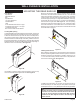
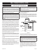
A drip leg should be installed in the vertical gas supply pipe run to
the wall furnace.
Manual Shut-off Valve
Some local regulations require the installation of a manual shut-off
valve and ground joint union external to the appliance. The shutoff
should be accessible for service and/or emergency use. Consult the
local utility or gas supplier for additional requirements regarding the
placement of the manual shut off valve. Compounds used on
threaded joints of gas piping shall be resistant to the action of liq-
ueed petroleum gases.
Leak Testing
WARNING - FIRE OR EXPLOSION HAZARD
Never test for leaks with an open ame. Check all connec-
tions using a commercially available soap solution. A re or
explosion may result causing property damage, personal
injury or loss of life. Failure to follow the safety warnings
exactly could result in serious injury, death or property
damage.
After gas piping to the wall furnace is complete, all connections
must be tested for gas leaks. This includes pipe connections at
the main gas valve, emergency shutoff valve and exible gas con-
nectors (if applicable). The soap and water solution can be applied
on each joint or union using a small paintbrush. If any bubbling is
observed, the connection is not sealed adequately and must be
retightened. Repeat the tightening and soap check process until
the bubbling ceases.
Notice: When pressure testing the gas supply lines at pres-
sures greater than ½ psig (14 in. w.c.), the gas supply piping
system must be disconnected from the appliance to prevent
damage to the gas control valve. If the test pressure is less
than or equal to ½ psig (14 in. w.c.), close the manual shut-off
valve.
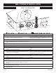
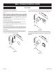
Pressure Testing of the Gas Supply System
1. To check the inlet pressure to the gas valve, a 1/8 inch N.P.T.
plugged tapping, accessible for test gauge connection, must
be placed immediately upstream of the gas supply connection
to the appliance.
2. The appliance and its individual shutoff valve must be discon-
nected from the gas supply piping system during any pres-
sure testing of that system at test pressures in excess of 1/2
psig.
3. The appliance must be isolated from the gas supply piping
system by closing its individual manual shutoff valve during
any pressure testing of the gas supply piping system at test
pressures equal to or less than 1/2 psig.
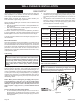
Recommended Gas Pipe Diameter
Pipe Length
Schedule 40 Pipe
Inside Diameter
Tubing, Type L
Outside Diameter
Nat. L.P. Nat. L.P.
0-10 feet
0-3 meters
1/2”
12.7 mm
3/8”
9.5mm
1/2”
12.7 mm
3/8”
9.5 mm
10-40 feet
4-12 meters
1/2”
12.7 mm
1/2”
12.7mm
5/8”
15.9 mm
1/2”
12.7 mm
40-100 feet
13-30 meters
1/2”
12.7 mm
1/2”
12.7mm
3/4”
19 mm
1/2”
12.7 mm
100-150 feet
31-46 meters
3/4”
19 mm
1/2”
12.7 mm
7/8”
22.2 mm
3/4”
19 mm
Table 1
Gas Supply Pressure NAT Gas L.P.
Normal 7.0” w.c. 10.0” w.c.
Minimum 3.5” w.c. 8.0” w.c.
Maximum 10.5” w.c. 13.0” w.c.
Manifold Pressure Hi (Level 5) 3.5” w.c. 7.0” w.c.
Manifold Pressure Low (Level 1) 0.9” w.c. 1.9” w.c.
Table 2
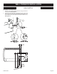
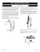
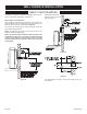
Gas Connection Installation
CAUTION
Under no circumstances should the gas supply line to the
appliance be installed in a way that would prevent the appli-
ance from being serviced or inspected.
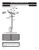
Figure 33
GAS SUPPLY
WALL FURNACE INSTALLATION