EMPIRE Comfort Systems INSTALLATION INSTRUCTIONS AND OWNER’S MANUAL The Direct Vent Zero Clearance Gas Fireplace Heater Direct vent Gas Fireplace heater Model series DVP36PP32EN-2 DVP36PP32EP-2 DVP36SP32EN-2 DVP36SP32EP-2 GAS-FIRED Installer: Leave this manual with the appliance. Consumer: Retain this manual for future reference. WARNING: If the information in these instructions are not followed exactly, a fire or explosion may result causing property damage, personal injury or loss of life.
TABLE OF CONTENTS Section Page Carton Contents...............................................................................................................................................................3 Hardware Package...........................................................................................................................................................3 Important Safety Information......................................................................................................
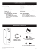
CARTON CONTENTS Fireplace Assembly Installation Package 3/8" x 12" Flexline Rockwool Packet Installation Instructions Serial Number Tag Recepticle, 3-Prong Warranty Card Cover, Junction Box Hardware Package (See Figure Below) Romex Connector (2) #10 x 1/2" Phillips Hex Head Screw #8-18 x 1/2" Phillips Truss Head Screw Nailing Flange Additional Parts for Peninsula Models Only: Canopy, End* Canopy, Right* Canopy, Left* End Shield* Canopy Corner Tie* *Note: Installation required when using EMP
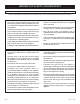
IMPORTANT SAFETY INFORMATION Before enclosing the vent pipe assembly, operate the appliance to ensure it is venting properly. DO NOT OPERATE THIS APPLIANCE WITHOUT ALL GLASS DOOR PANELS INSTALLED • If this appliance is installed directly on carpeting, tile or other combustible material other than wood flooring the appliance shall be installed on a metal or wood panel extending the full width and depth of the appliance. placed on or near the appliance.
SAFETY INFORMATION FOR USERS OF LP GAS by point with the members of your household. Someday when there may not be a minute to lose, everyone’s safety will depend on knowing exactly what to do. If, after reading the following information, you feel you still need more information, please contact your gas supplier. Propane (LP-Gas) is a flammable gas which can cause fires and explosions. In its natural state, propane is odorless and colorless.
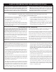
REQUIREMENTS FOR MASSACHUSETTS For all side wall horizontally vented gas fueled equipment installed in every dwelling, building or structure used in whole or in part for residential purposes, including those owned or operated by the Commonwealth and where the side wall exhaust vent termination is less than seven (7) feet above finished grade in the area of the venting, including but not limited to decks and porches, the following requirements shall be satisfied: 1.
INTRODUCTION Instructions to Installer 1. Installer must leave instruction manual with owner after installation. 2. Installer must have owner fill out and mail warranty card supplied with the fireplace. 3. Installer should show owner how to start and operate the fireplace. This direct vent gas fireplace heater is designed to operate with all combustion air being siphoned from the outside of the building and all exhaust gases expelled to the outside of the building.
SPECIFICATIONS DVP36(SP,PP) Nat Models Input Btu/hr Maximum Btu/hr Minimum (millivolt only) KWH (Maximum) (Minimum) 35,000 24,000 10.15 6.
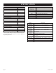
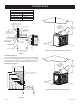
FIREPLACE DIMENSIONS HORIZONTAL VENT CONNECTION 7 7 C C SEE THRU 31 7/8 K K L L N D M PENINSULA A H D N M 31 32 ½ E B I G J J F 32 ½ E B A H I 17 ½ 21 Figure 1 MODEL A B C D E F G H I J K L M N MAX WEIGHT (LB) 26591-1-1209 DVP36SP32E 34 3/4” 39" 24” 22" 36” 29 1/4” 22” 41 1/8” 1 1/4” 5 3/8" 2 1/2” 6” 25" 33 1/2” 240 DVP36PP32E 34 3/4” 39" 24” 22" 36” 32 5/8” 22” 41 1/8” 1 1/4” 5 3/8" 2 1/2” 6” 25" 33 1/2” 230 Page 9
CLEARANCES Clearance to Combustibles Air Drop (End) 1/2" (12.7 mm) Side 1/2" (12.7 mm) Floor 0" (0 mm) Top Stand-off 0" (0 mm) Top Framing Edge 6 3/8" (161.7 mm) SEE MANTLE CHART FOR MAXIMUM MANTLE DEPTH 1 3/4” MIN. PERPENDICULAR COMBUSTIBLE SIDEWALL 2” x 4” HEADER 42” MIN.
OPTIONAL EMPT SERIES MANTLE INSTALLATION - PENINSULA MODELS ONLY The Peninsula Direct Vent fireplaces include a 3-Piece Canopy and End Shield. These additional parts must be installed on the fireplace if the EMPT series Mantel top is to be used. Note: The 3-piece canopy and End Shield is not required if the fireplace is to be finished off using an installation method as shown in Figure 4b.
LOCATING FIREPLACE Note:** Island (C) and Room Divider (D) installation is possible as long as the horizontal portion of the vent system (H) does not exceed 20 feet with a minimum vertical run of 8 feet. See details in Venting Section. *When you install your Direct Vent Fireplace, a minimum of 1 3/4 inches clearance must be maintained from the perpendicular wall and the front opening of the appliance.
GAS SUPPLY The gas pipeline can be brought in through the right or left side of the appliance. Consult the current National Fuel Gas Code, ANSI Z223.1 CAN/CGA-B149 (.1 or .2) installation code. Recommended Gas Pipe Diameter Pipe Length Schedule 40 Pipe Inside Diameter Tubing, Type L Outside Diameter Nat. L.P. Nat. L.P. 0-10ft 0-3m 1/2" 12.7mm 3/8" 9.5mm 1/2" 12.7mm 3/8" 9.5mm 11-40ft 4-12m 1/2" 12.7mm 1/2" 12.7mm 5/8" 15.9mm 1/2" 12.7mm 41-100ft 13-30m 1/2" 12.7mm 1/2" 12.
REAR VENT CONVERSION HORIZONTAL VENTING VERTICAL VENTING Note: It is recommended that the flue cover plate tab be pulled outward prior to removal. INLET VENT COVER PLATE INLET VENT COLLAR This will ensure that the plate is not accidentally dropped inside the rear air chamber. FLUE COVER PLATE FLUE OUTLET COLLAR FLUE COVER PLATE (See note above.
PLANNING INSTALLATION In planning the installation for the fireplace, it is necessary to determine where the unit is to be installed and whether optional accessories are desired. Gas supply piping should also be planned at this time. A gas shutoff must be installed in this line. If the fireplace is installed directly on carpeting, tile or other combustible material other than wood flooring, it should be installed on a metal or wood panel extending the full width and depth of the unit.
FIREPLACE INSTALLATION INSTRUCTIONS (continued) Locating Fireplace Place fireplace in framed opening. Attach the framing brackets to the fireplace and secure to framing. Different hole locations can be used for finishing materials with thicknesses of 3/8", 1/2" and 3/4". Secure the brackets with screws provided using two (2) per framing bracket. See Figure 13. Framing brackets should fit directly against framing material. Use at least one (1) nail or screw per bracket to secure in place.
INSTALLATION Flush Mount Mantel Installation - See-through Models Only (Figure 15) The fireplace must extend 3/4" beyond finished wall surface when using a flush mount mantel on see-through models. Refer to Figure 15 to locate nailing flanges on fireplace sides. Use eight (8) 1/2" hex-head screws supplied in hardware package to attach nailing flanges to fireplace sides. Note: For finishing to top of fireplace, refer to Figure ______. Attention: Add 3-3/4" to “A” dimensions when using a flush mantel base.
Vent Pipe Clearance Note: Maintain one inch (1") of clearance around vertical vent pipe. See Figure 18. For horizontal vent, maintain a minimum 1" clearance to the bottom and sides of the vent, and 3" clearance to combustibles above the vent pipe. See Figure 19.
INSTALLATION (continued) Horizontal only, straight out the back “A” PIPE LENGTH VENT CAP WALL FIRESTOP/ THIMBLE “B” "A" "B" 6" 5 1/8" to 6 1/2" 9" 8 1/8" to 9 1/2" 12" 11 1/8" to 12 1/2" Figure 20 vertical, 90° elbow to horizontal out the wall “A” PIPE LENGTH 90º ELBOW 9” (229 MM) MINIMUM VENT CAP NOTE: 1 FOOT VERTICAL VENT (MIN.
VENTING FIREPLACE - TOP EXAMPLE A: (Top Vent Connections with Vertical Termination). If the vertical dimension from the floor of the unit is 35 feet, the horizontal run to the outer wall flange must not exceed 6.5 feet. EXAMPLE B: (Top Vent Connections with Vertical Termination) If the vertical dimension from the floor of the unit is 6.5 feet, the horizontal run to the outer wall flange must not exceed 14.5 feet.
VENTING FIREPLACE - TOP (continued) Below Grade Installation When it is not possible to meet the required vent terminal clearances of 12" (305mm) above grade level, a snorkel kit is recommended. See page 38. It allows installation depth down to 7" (178mm) below grade level. The 7" (178mm) is measured from the center of the horizontal vent pipe as it penetrates through the wall. Ensure the sidewall venting clearances are observed.
10” (254mm) C SEE VENT CHART FOR PERMISSIBLE “H” AND “V” DIMENSIONS VENT CAP B 11” (279mm) V H 1 FOOT VERTICAL PIPE REQUIRED (MINIMUM) C B 9” (229 MM) MINIMUM A CENTER OF ELBOW STRAIGHT OUT (MINIMUM) NOTE: 1 FOOT SECTION (MIN.) OF VERTICAL VENT REQUIRED WHEN USING HORIZONTAL TERMINATION OFF TOP. Figure 27 2’ MAX. (609.
DVVK-4FV DIRECT VENT TERMINATION KIT Installation Instructions This termination kit can only be used with Empire Comfort Systems direct vent fireplaces listed for use with DVVK-4FV Vertical Flex Vent Kit. Please review the instructions packaged with your fireplace and verify the fireplace model number. Check that this flex vent system is listed for use with your fireplace model prior to starting the installation.
PRE-INSTALLATION INFORMATION: Items Required For Installation: Tools Phillips Screwdriver Hammer Saw and/or saber saw Level Measuring Tape Electric Drill and Bits Pliers Square Tin Snips Building Supplies Framing Materials Wall Finishing Materials Caulking Material (Noncombustible) Support Strap supplies Before You Start: Plan your installation. Read these instructions and the fireplace installation manual before installing unit and vent system. Set unit in place and survey how best to vent the unit.
DVVK-4FV DIRECT VENT TERMINATION KIT (continued) Step-By-Step Installation For Flex DV Kit 1. 2. 3. 4. Unpack vent components and check all items for shipping damage. For this venting system to operate as designed it is dependent on the use of all parts and procedures detailed in these instructions. Failure to follow these instructions may potentially affect the performance of this vent system and the attached appliance.
DVVK-4FV DIRECT VENT TERMINATION KIT (continued) 10. With the flex vent assembly and the 48” long hard pipe components laid out on the floor, begin securing these parts together. First, apply a generous bead of silicone sealant to the inside of the 4” diameter flex flue (not the end with the pre-installaed connector), then slide the flex flue over the 4” diameter hard pipe flue. Be sure to overlap at least 1-1/4”. Secure this connection with a 4” diameter band clamp provided.
DVVK-4FV DIRECT VENT TERMINATION KIT (continued) 17. To attach the vent connections at the fireplace, be sure the 7” diameter adapter collar has been installed per step 3. Apply a bead of silicone sealant to the 4” diameter flex connector, then slide the flex pipe adapter collar into the fireplace flue collar and secure by installing a minimum of two (2) screws through the flue collar and into the adapter. See Figure 33. 18.
DVVK-4FV DIRECT VENT TERMINATION KIT (continued) VERTICAL TERMINATION STORM COLLAR 4’ LONG RIGID PIPE ROOF FLASHING ADJUSTABLE ROOF JACK ASSEMBLY CLEARANCE TO COMBUSTIBLES REQUIRED FROM VENT PIPE ADJUSTABLE FIRESTOP/THIMBLE ASSEMBLY ROOF EXTERIOR CLAMPS AT FLUE & INLET VENT CONNECTIONS STORM COLLAR (USE TO KEEP INSULATION OUT OF THIMBLE ASSEMBLY) CEILING FIRESTOP/THIMBLE VENTING SUPPORT STRAPS (AS REQ’D) 35’ MAX NOTE: DVVK-4FV KIT MAXIMUM HEIGHT (INCLUDING FIREPLACE) IS 13’.
DVVK-4FV DIRECT VENT TERMINATION KIT (continued) Vertical Flex Termination Kit Item Number 1 2 3 4 5 6 7 8 9 10 N/S N/S N/S N/S N/S 26591-1-1209 Item Description 4”/7” Vertical Termination Cap Roof Support Kit 2 Ply Alum Flex 4” Diameter by 6 ft. 2 Ply Alum Flex 7” Diameter by 6 ft.
EXAMPLES - TOP VENT RUN 24” 24” MINIMUM CLEARANCE TO COMBUSTIBLES Example H2 3ft, H3 1ft = 4ft (90° + 90° + 90°) = 6ft V1 = 21ft H = 10ft V = 21ft Figure 37 Example H2 = 2ft 2 - (90° + 90°) = 6ft V1 = 21ft H = 8ft V = 15ft Figure 36 Example H1 = 2ft V1 = 20ft H = 2ft Figure 38 Page 30 V = 20ft 26591-1-1209
VENTING FIREPLACE - REAR EXAMPLE A: If the vertical dimension from the floor of the unit is 12 feet, 4 inches the horizontal run to the outer wall flange must not exceed 12 feet, 3 inches. EXAMPLE B: If the vertical dimension from the floor of the unit is 6 feet, 9 inches, the horizontal run to the outer wall flange must not exceed 6 feet, 6 inches. Special Note: For each 45 degree elbow installed in the horizontal run, the length of the horizontal run MUST be reduced by 18" (45cm).
EXAMPLES - REAR VENT RUN Model DVP36(SP,PP) Maximum Pipe Length H1 18" H1 = 18” MAX.
TERMINATION CLEARANCES Termination clearance for buildings with combustible and noncombustible exteriors. Figure 44 Vertical Sidewall Installations Important! Minimum clearance between vent pipes and combustible materials is three (3") (76mm) on top, and (1") (25mm) on bottom and sides. Important! When vent termination exits through foundation less than 20" below siding outcrop, the vent pipe must extend outward so that the horizontal vent terminal is located flush to, or beyond the outcrop siding.
VENT CLEARANCES Figure 45 A= *Clearance above grade, veranda, porch, deck or balcony [*12 inches (30cm) minimum] B= clearance to window or door that may be opened [*12 inches (30cm) minimum for appliances < 100,000 Btuh (30kW) C= clearance to permanently closed window [minimum 12 inches (30cm) recommended to prevent condensation on window] D= vertical clearance to ventilated soffit located above the terminal within a horizontal distance of 24 inches (60 cm) from the center of the terminal [18 Inches
VENT SYSTEM IDENTIFICATION Installing Vent Components (Figure 46) Begin the vent system installation by installing the first Simpson Duravent component, 90° elbow to the starting collars or straight pipe on the top of the appliance, then the straight pipe length and then horizontal or vertical termination kit. NOTE: All outer connection joints must be sealed with aluminum tape, screws or silicone sealant rated above 300°F/149°C. The inner flue joints do not require any sealant.
FRAMING AND FINISHING Installing Support Brackets (Figure 47) A horizontal pipe support MUST BE used for each 3 feet of horizontal run. The pipe supports should be placed around the pipe and nailed in place to framing members. There MUST BE a 3 inch clearance to combustibles above 6 5/8 inch diameter pipe and elbows and 1 inch clearance on both sides and bottom of 6 5/8 inch pipe to combustibles on all horizontal pipe sections and elbows.
FRAMING AND FINISHING (continued) Figure 49 Figure 51 Figure 50 26591-1-1209 Page 37
HORIZONTAL TERMINATION NOTE: Termination cap should pass through the wall firestop from the exterior of the building. Adjust the termination cap to its final exterior position on the building. Warning: Termination cap must be positioned so that arrow is pointing up. Attach the termination cap with the four wood screws provided. Before attachment of the termination, run a bead of silicone sealant rated above 250°F on its outside edge too, so as to make a seal to the exterior wall.
DVVK-4RE VENT KIT INSTALLATION INSTRUCTIONS CAUTION: Sharp edges, use protective gloves when installing. Tools Needed for Installation: Sheet metal snips 5/16” nut driver Phillips head screwdriver - #2 High temperature sealant or furnace cement rated for continuous use at 1,000oF minimum Measuring tape NOTE: SPACING FLANGE INSTALLED TO TOPSIDE 11” EXTENSION THIMBLE Parts Verification See parts list on page 41 to verify components included in this vent kit prior to installation.
DVVK-4RE VENT KIT INSTALLATION INSTRUCTIONS (continued) 8. Attach the 4” (102mm) diameter flue outlet tube onto the rigid venting system or directly to fireplace. Ensure the 4” (102mm) diameter flue outlet tube is placed as far as possible onto the rigid venting system. Mark the 4” (102mm) diameter flue outlet tube 2 1/2” (64mm) beyond the vinyl siding kit or wall. See Figure 57. Remove the 4” (102mm) diameter flue outlet tube from rigid venting system.
DVVK-4RE VENT KIT INSTALLATION INSTRUCTIONS (continued) Follow correct option according to venting method. Connecting Directly to Fireplace If the air inlet and flue outlet tubes are to be connected directly to the unit (no rigid venting system is being used), then the gasket provided must be used to seal the 4” (102mm) flue outlet tube. Peel the paper off the self-adhesive gasket and then wrap it around the end of the tube (if tube was cut, it is recommended to use cut end) as shown in Figure 58.
DVVK-4F FLEX VENT INSTRUCTIONS The DVVK-4F FLEX VENT KIT includes the following components: • (1) Horizontal Termination Cap • (1) 7" diameter Outer Vent adapter collar • (1) 4-foot section of Flex vent with spacers (4" flue/7" outer • (1) Wall Firestop/Thimble Assembly pipe) • Hardware pack that includes band clamps and screws • (1) 4" diameter Flue adapter collar Flex venting can be installed either vertically or horizontally off of the DVP36 Series fireplaces.
VERTICAL TERMINATION Locate and mark the center point of the venting pipe. Using a nail on the underside of the roof and drive this nail through this center point. Make the outline of the roof hole around this center point. When terminating the vent cap near an exterior wall or overhang, maintain minimum clearances as shown in Figure 60. NOTE: Size of the roof hole dimensions depend on the pitch of the roof. There must be a 1 inch clearance (25mm) to the vertical pipe sections.
VERTICAL TERMINATION (continued) NOTE: When installing this vent system in a chase, it is always good building practice to insulate the chase as you would the outside walls of your home. This is especially important for cold climate installations. Upon completion of building your chase framing, install the vent system by following the instructions in this manual.
PLACEMENT OF GLOWING EMBERS Placement of the glowing embers (rockwool) is very individual and light coverage of the areas indicated will provide your best effects. We recommend separation of the rockwool by hand and to make your coverage as light and fluffy as possible. Place just enough embers on the burner to obtain the glow and a gold yellow flame. Do not place rockwool over large port areas. Rockwool should not be placed in the area of the pilot assembly.
OPERATION INSTRUCTIONS/FLAME APPEARANCE Before you begin: Do not handle the logs with your bare hands! Always wear gloves to prevent skin irritation. After handling logs, wash your hands gently with soap and water. All Logs The positioning of the logs is critical to the safe and clean operation of this heater. Sooting and other problems may result if the logs are not properly and firmly positioned in the appliance. Instructions for placement of the logs in the fireplace are included with the logset.
OPERATING INSTRUCTIONS 750 Millivolt System The standing pilot (750 millivolt system) is a continuous burning pilot. The pilot remains ON even when the main burner is OFF. When you ignite the pilot, the thermopile produces millivolts (electrical current) which energizes the magnet in the gas valve. After 30 seconds to 1 minute time period you can release the gas control knob and the pilot will stay ON.
OPERATING INSTRUCTIONS (continued) standing pilot Operating Instructions Remote/Off/On Switch The fireplace is equipped with a Remote/OFF/ON switch. A wire harness is attached to the Remote/OFF/ON switch. The red, black and green (wires) female push-ons attach to the Remote/OFF/ON switch. At the opposite end of the wire harness, the black and green (wires) female push-ons attach to the gas valve.
STANDING PILOT WIRING DIAGRAM (OPTIONAL) THERMOSTAT (OPTIONAL) WALL SWITCH Figure 66 26591-1-1209 Page 49
STANDING PILOT LIGHTING INSTRUCTIONS FOR YOUR SAFETY READ BEFORE LIGHTING Warning: If you do not follow these instructions exactly, a fire or explosion may result causing property damage, personal injury or loss of life. A. This appliance has a pilot which must be lighted by hand. When lighting the pilot, follow these instructions exactly. B. Before lighting smell all around the appliance area for gas. Be sure to smell next to the floor because some gas is heavier than air and will settle on the floor.
STANDING PILOT TROUBLESHOOTING With proper installation and maintenance, your new Direct Vent Gas Fireplace will provide years of trouble-free service. If you do experience a problem, refer to the Trouble Shooting Guide below. This guide will assist a qualified service person in the diagnosis of problems and the corrective action to be taken. 1. Spark ignitor will not light pilot after repeated triggering of piezo ignitor button. a.
MAINTENANCE AND SERVICE Please Note It is normal for appliances fabricated of steel to give off some expansion and/or contraction noise during the start up or cool down cycle. Similar noises are found with your furnace heat exchanger or car engine. It is not unusual for your gas fireplace to give off some odor the first time it is burned. This is due to the curing of the paint and any undetected oil from the manufacturing process. Please ensure that your room is well ventilated - open all windows.
PARTS LIST PART NO. INDEX NO. DVP36SP DVP36PP 1 24316 24316 PART NO. INDEX NO.
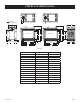
DVP36SP PARTS VIEW 17 17 16 14 15 13 2 12 11 3 10 9 8 7 6 5 5 52 5 5 5 5 4 5 2 40 1 3 41 42 43 37 39 44 4 38 36 35 34 22 18 23 24 22 18 24 25 25 20 40 26 27 28 19 30 29 21 31 33 32 Page 54 26591-1-1209
DVP36PP PARTS VIEW 17 17 16 14 15 13 12 47 46 2 45 11 10 3 9 48 8 7 6 49 5 5 5 50 52 5 4 2 40 1 3 41 42 43 37 39 44 4 38 36 35 34 22 18 51 23 24 24 25 25 20 40 26 27 28 19 30 29 21 31 33 32 26591-1-1209 Page 55
WIRING INSTRUCTIONS FOR INSTALLING A DUAL SWITCH / RECEPTACLE In order to install both the optional Blower and Accent Light accessories, it will be necessary to install the junction box so that the Duplex Receptacle wiring is split. This will allow each side of the receptacle to operate independently off separate wall switches. See diagram below. CAUTION: ALL WIRING SHOULD BE DONE BY A QUALIFIED ELECTRICIAN AND SHALL BE IN COMPLIANCE WITH ALL LOCAL, CITY AND STATE BUILDING CODES.
ACCENT LAMP Your Direct Vent Gas Fireplace comes equipped with an "Accent Lamp." The light has been pre-wired and is controlled from the Rheostat. If in the event the lamp or lens needs to be replaced, follow the instructions below: 1. Unplug the Accent Lamp/transformer from the junction box inside the fireplace. 2. Remove the four screws that secure the lens frame. This frame retains the glass lens. The bulb can now be accessed.
OPTIONAL FBB5 BLOWER INSTALLATION INSTRUCTIONS Attention: Install blower assembly before connecting gas inlet supply line. Wiring The appliance, when installed, must be electrically grounded in accordance with local codes or, in the absence of local codes, with the National Electrical Code, ANSI/NFPA 70, if an external electrical source is utilized.
OPTIONAL BLOWER INSTALLATION INSTRUCTIONS (continued) 4. 5. 6. Insert blower assembly into interior, bottom of fireplace. Note: On peninsula models, the blower must be installed at the end which has the brick panel installed. Position blower assembly so that you align the notch on back of blower assembly with the center screw on side/end panel, then push the blower assembly against fireplace outer panel. The blower wheel must be centered with the side/end wall of the fireplace.
OPTIONAL BLOWER INSTALLATION INSTRUCTIONS (continued) Wiring The appliance, when installed, must be electrically grounded in accordance with local codes or, in the absence of local codes, with the National Electrical Code, ANSI/NFPA 70, if an external electrical source is utilized. This appliance is equipped with a three-prong [grounding] plug for your protection against shock hazard and should be plugged directly into a properly grounded three-prong receptacle.
ACCESSORIES The following accessory parts can be obtained from your Empire Comfort Systems dealer. If you need additional information beyond what your dealer can furnish, contact Empire Comfort Systems Inc., Nine Eighteen Freeburg Ave., Belleville, Illinois 62220-2623. Accessory Fan Kit Description Model Numbers 2 1 Designed to provide forced air flow.
HOW TO ORDER REPAIR PARTS Parts can be ordered only through your service person or dealer. For best results, the service person or dealer should order parts through the distributor. Parts can be shipped directly to the service person/dealer. All parts listed in the Parts List have a Part Number. When ordering parts, first obtain the Model Number from the name plate on your equipment.
SERVICE NOTES 26591-1-1209 Page 63
EMPIRE Comfort Systems Empire Comfort Systems Inc. 918 Freeburg Ave. Belleville, IL 62220 If you have a general question about our products, please e-mail us at info@empirecomfort.com. If you have a service or repair question, please contact your dealer. www.empirecomfort.