EMPIRE Comfort Systems INSTALLATION INSTRUCTIONS AND OWNER’S MANUAL Direct Vent Zero Clearance Gas Fireplace Heater LUXURY DIRECT VENT GAS FIREPLACE HEATER MODEL SERIES MILLIVOLT STANDING PILOT GAS-FIRED DVX36FP32CL(N,P)-2 DVX36FP33CL(N,P)-2 DVX36FP31L(N,P)-1 DVX42FP32CL(N,P)-2 DVX42FP33CL(N,P)-2 DVX42FP31L(N,P)-1 DIRECT IGNITION WARNING HOT GLASS WILL CAUSE BURNS. DO NOT TOUCH GLASS UNTIL COOLED. NEVER ALLOW CHILDREN TO TOUCH GLASS.
Section TABLE OF CONTENTS Page Important Safety Information..........................................................................................................................................2 Safety Information for Users of LP Gas..........................................................................................................................4 Requirements for Massachusetts......................................................................................................................
IMPORTANT SAFETY INFORMATION Before enclosing the vent pipe assembly, operate the appliance to ensure it is venting properly. DO NOT OPERATE THIS APPLIANCE WITHOUT GLASS FRONT PANEL INSTALLED • If this appliance is installed directly on carpeting, tile or other combustible material other than wood flooring the appliance shall be installed on a metal or wood panel extending the full width and depth of the appliance. The base referred to above does not mean the fireproof base as used on wood stoves.
SAFETY INFORMATION FOR USERS OF LP GAS Propane (LP-Gas) is a flammable gas which can cause fires and explosions. In its natural state, propane is odorless and colorless. You may not know all the following safety precautions which can protect both you and your family from an accident. Read them carefully now, then review them point by point with the members of your household. Someday when there may not be a minute to lose, everyone’s safety will depend on knowing exactly what to do.
REQUIREMENTS FOR MASSACHUSETTS For all side wall horizontally vented gas fueled equipment installed in every dwelling, building or structure used in whole or in part for residential purposes, including those owned or operated by the Commonwealth and where the side wall exhaust vent termination is less than seven (7) feet above finished grade in the area of the venting, including but not limited to decks and porches, the following requirements shall be satisfied: 1.
INTRODUCTION Instructions to Installer 1. Installer must leave instruction manual with owner after installation. 2. Installer must have owner fill out and mail warranty card supplied with the fireplace. 3. Installer should show owner how to start and operate the fireplace. This direct vent gas fireplace heater is designed to operate with all combustion air being siphoned from the outside of the building and all exhaust gases expelled to the outside of the building.
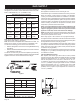
SPECIFICATIONS DVX36 NAT DVX36 LP DVX42 NAT DVX42 LP Input Btu/hr Maximum 35,000 30,000 37,500 35,000 Btu/hr Minimum 24,000 21,000 26,000 24,000 KWH (Maximum) 10.3 8.8 11.0 10.3 (Minimum) 7.2 6.2 7.6 7.2 Orifice #32 (P-211) 1.65mm (P-250) #31 (P-209) DVX42FP(3,7,9) 2.75 mm (P-305) - DVX42FP5 #50 (P-245) - DVX42FP(3,7,9) 1.80 mm (P-304) - DVX42FP5 Air Shutter Opening 1/4"(6.4mm) FULL OPEN 1/4" (6.4mm) FULL OPEN Height without standoff 34 3/4 (3.2mm) 34 3/4" (3.
CLEARANCES Mantel Chart (Figure 4) Clearance to Combustibles Back 0" (0 mm) Side 0" (0 mm) Floor 0" (0 mm) Top Stand-off 0" (0 mm) Top Framing Edge 6" (152 mm) 12” (305mm) 10” (254mm) MANTEL COMBUSTIBLE TRIM AND MANTELS ALLOWED IN SHADED AREA 8” 6” 19” 4 1/2” 3 3/4” 3” 18 3/4” 2 1/4” 1 1/2” 17” 16” 15” 3/4” 14” 13” 12” 11” 10” TOP EDGE OF FIREPLACE Figure 4 Clearances (Figure 5) Clearance from top front edge of fireplace to ceiling is 36" Clearance from side of fireplace to adjacent sidewall i
LOCATING FIREPLACE Note: Island (C) and Room Divider (F) installation is possible as long as the horizontal portion of the vent system (H) does not exceed 20 feet with a minimum vertical run of 8 feet. See details in Venting Section. When you install your Direct Vent Fireplace in (F) Room divider or (A) Flat on wall corner positions, a minimum of 6 inches clearance must be maintained from the perpendicular wall and the front edge of the appliance.
GAS SUPPLY The gas pipeline can be brought in through the right or left side of the appliance. Consult the current National Fuel Gas Code, ANSI Z223.1 CAN/CGA-B149 (.1 or .2) installation code. Recommended Gas Pipe Diameter Pipe Length Schedule 40 Pipe Inside Diameter Tubing, Type L Outside Diameter Nat. L.P. Nat. 0-10ft 0-3m 1/2" 12.7mm 3/8" 9.5mm 1/2" 3/8" 12.7mm 9.5mm 11-40ft 4-12m 1/2" 12.7mm 1/2" 12.7mm 5/8" 1/2" 15.9mm 12.7mm 41-100ft 13-30m 1/2" 12.7mm 1/2" 12.
INSTALLATION Framing and Finishing 1. Choose unit location. 2. Frame in fireplace with a header across the top. It is important to allow for finished face when setting the depth of the frame. 3. Attach fireplace to frame using adjustable frame. Preset depth to suit facing material (adjustable to 1/2", 5/8" or 3/4" depths). 4. Use (8) 1/2" hex-head screws supplied in hardware package, to screw through slotted holes in drywall strip and then screw into pre-drilled holes on fireplace side.
INSTALLATION (continued) Flush Mount Mantel Installation (Figure 12) The fireplace must extend 3/4" beyond finished wall surface when using a flush mount mantel. Refer to Figure 12 to locate nailing flanges on fireplace sides. Mark and drill two (2) 1/8" holes into fireplace side to mount each nailing flange. Use eight (8) 1/2" hexhead screws supplied in hardware package to attach nailing flanges to fireplace sides.
Flush Wall Installation Attention: Cold climate installation recommendation: When installing this unit against a non-insulated exterior wall, it is recommended that the outer walls be insulated to conform to applicable insulation codes. Vent Runs (Figures 16, 17, and 18) In planning the installation for the fireplace, it is necessary to install certain components before the appliance is completely positioned and installed.
INSTALLATION (continued) VERTICAL, 90° ELBOW TO HORIZONTAL OUT THE WALL CORNER INSTALLATION VERTICAL, 90° ELBOW TO HORIZONTAL OUT THE WALL “A” PIPE LENGTH 90º ELBOW WALL FIRESTOP/ THIMBLE “A” “B” 6” (152mm) MINIMUM “C” VENT CAP 9” (229mm) MINIMUM “D” VENT CAP WALL FIRESTOP/ THIMBLE “C” “B” "A" "B" "C" 6"(152mm) 11 1/4"(286mm) to 12 3/4"(324mm) 4 3/4"(121mm) to 6 1/4"(159mm) 9"(229mm) 14 1/4"(362mm) to 15 3/4"(400mm) 7 3/4"(197mm) to 9 1/4"(235MM) 12"(305mm) 17 1/4"(438mm) to 18 3/4"(476
VENTING FIREPLACE - TOP To Use the Vent Graph (Figure 19) 1. Determine the height of the center of the horizontal vent pipe. Using this dimension on the Sidewall Vent Graph, locate the point it intersects with the slanted graph line. 2. From the point of this intersection, draw a vertical line to the bottom of the graph. 3. Select the indicated dimension, and position the unit in accordance with same.
VENTING FIREPLACE - TOP (continued) Below Grade Installation When it is not possible to meet the required vent terminal clearances of 12" (305mm) above grade level, a snorkel kit is recommended. It allows installation depth down to 7" (178mm) below grade level. The 7" (178mm) is measured from the center of the horizontal vent pipe as it penetrates through the wall. Ensure the sidewall venting clearances are observed.
10” (254mm) C B 12” (305mm) V H SEE CHART FOR PERMISSIBLE “H” AND “V” DIMENSIONS C B A CENTER OF ELBOW STRAIGHT OUT (MINIMUM) Figure 24 Figure 23 MINIMUM HOLE LOCATION DIMENSIONS FOR THROUGH THE WALL HORIZONTAL INSTALLATIONS WITH 90 DEGREE ELBOW OFF TOP OF FIREPLACE Positioning the Fireplace FIREPLACE HARD ELBOW DIMENSIONS SERIES "A" "B" "C" DVX36FP 43-1/2" 5" 7" (1105mm) (127mm) (178mm) DVX42FP 43-1/2" 5" 7" (1105mm) (127mm) (178mm) FIREPLACE SERIES DVX36FP DVX42FP FLEX PIPE 90 DEGREE BEND "A" "B" "
EXAMPLES - TOP VENT RUN 24” 24” MINIMUM CLEARANCE TO COMBUSTIBLES Example H2 3ft, H3 1ft = 4ft (90° + 90° + 90°) = 6ft V1 = 21ft H = 10ft V = 21ft Figure 27 Example H2 = 2ft 2 - (90° + 90°) = 6ft V1 = 21ft H = 8ft V = 15ft Figure 26 Example H1 = 2ft V1 = 20ft H = 2ft V = 20ft Figure 28 Page 18 30329-0-0312
DVVK-4RE VENT KIT INSTALLATION INSTRUCTIONS CAUTION: Sharp edges, use protective gloves when installing. Tools Needed for Installation: Sheet metal snips 5/16” nut driver Phillips head screwdriver - #2 High temperature sealant or furnace cement rated for continuous use at 1,000oF minimum Measuring tape NOTE: SPACING FLANGE INSTALLED TO TOPSIDE 11” Parts Verification See parts list on page 21 to verify components included in this vent kit prior to installation.
DVVK-4RE VENT KIT INSTALLATION INSTRUCTIONS (continued) 7. Remove outside mounting plate with tube attached from wall. Mark and cut the extra length of the 6 5/8” (168mm) diameter tube from the opposite end. Do not crimp or enlarge tube. VINYL SIDING KIT DV822 OUTSIDE MOUNTING PLATE 8. Attach the 4” (102mm) diameter flue outlet tube onto the rigid venting system or directly to fireplace. Ensure the 4” (102mm) diameter flue outlet tube is placed as far as possible onto the rigid venting system.
DVVK-4RE VENT KIT INSTALLATION INSTRUCTIONS (continued) Follow correct option according to venting method. Connecting Directly to Fireplace If the air inlet and flue outlet tubes are to be connected directly to the unit (no rigid venting system is being used), then the gasket provided must be used to seal the 4” (102mm) flue outlet tube. Peel the paper off the self-adhesive gasket and then wrap it around the end of the tube (if tube was cut, it is recommended to use cut end) as shown in Figure 33.
DVVK-4FV DIRECT VENT TERMINATION KIT Installation Instructions This termination kit can only be used with Empire Comfort Systems direct vent fireplaces listed for use with DVVK-4FV Vertical Flex Vent Kit. Please review the instructions packaged with your fireplace and verify the fireplace model number. Check that this flex vent system is listed for use with your fireplace model prior to starting the installation.
DVVK-4FV DIRECT VENT TERMINATION KIT (cont.) PRE-INSTALLATION INFORMATION: Items Required For Installation: Tools Building Supplies Phillips Screwdriver Hammer Saw and/or saber saw Level Measuring Tape Electric Drill and Bits Pliers Square Tin Snips Framing Materials Wall Finishing Materials Caulking Material (Noncombustible) Support Strap supplies Before You Start: Plan your installation. Read these instructions and the fireplace installation manual before installing unit and vent system.
DVVK-4FV DIRECT VENT TERMINATION KIT (cont.) Step-By-Step Installation For Flex DV Kit 1. 2. 3. 4. 5. Unpack vent components and check all items for shipping damage. For this venting system to operate as designed it is dependent on the use of all parts and procedures detailed in these instructions. Failure to follow these instructions may potentially affect the performance of this vent system and the attached appliance.
DVVK-4FV DIRECT VENT TERMINATION KIT (cont.) 10. With the flex vent assembly and the 48” long hard pipe components laid out on the floor, begin securing these parts together. First, apply a generous bead of silicone sealant to the inside of the 4” diameter flex flue (not the end with the pre-installed connector), then slide the flex flue over the 4” diameter hard pipe flue. Be sure to overlap at least 1-1/4”. Secure this connection with a 4” diameter band clamp provided.
DVVK-4FV DIRECT VENT TERMINATION KIT (cont.) 17. To attach the vent connections at the fireplace, be sure the 7” diameter adapter collar has been installed per step 3. Apply a bead of silicone sealant to the 4” diameter flex connector, then slide the flex pipe adapter collar into the fireplace flue collar and secure by installing a minimum of two (2) screws through the flue collar and into the adapter. See Figure 39. 18.
DVVK-4FV DIRECT VENT TERMINATION KIT (cont.) VERTICAL TERMINATION STORM COLLAR 4’ LONG RIGID PIPE ROOF FLASHING ADJUSTABLE ROOF JACK ASSEMBLY ROOF EXTERIOR CLEARANCE TO COMBUSTIBLES REQUIRED FROM VENT PIPE CLAMPS AT FLUE & INLET VENT CONNECTIONS ADJUSTABLE FIRESTOP/THIMBLE ASSEMBLY CEILING STORM COLLAR (USE TO KEEP INSULATION OUT OF THIMBLE ASSEMBLY) FIRESTOP/THIMBLE VENTING SUPPORT STRAPS (AS REQ’D) 35’ MAX 4” DIA. FLUE CONNECTOR NOTE: DVVK-4FV KIT MAXIMUM HEIGHT (INCLUDING FIREPLACE) IS 13’.
DVVK-4FV DIRECT VENT TERMINATION KIT (cont.) Vertical Flex Termination Kit Item Number Page 28 Item Description Repair Part No. Quantity Supplied 1 4”/7” Vertical Termination Cap MF100038 1 2 Roof Support Kit MF100503 1 3 2 Ply Alum Flex 4” Diameter by 6 ft. MF04ALA2F006 1 4 2 Ply Alum Flex 7” Diameter by 6 ft.
DVVK-4F FLEX VENT INSTRUCTIONS The DVVK-4F FLEX VENT KIT includes the following components: • • • (1) Horizontal Termination Cap (1) 4-foot section of Flex vent with spacers (4" flue/7" outer pipe) (1) 4" diameter flue adapter collar • • • (1) 7" diameter outer vent adapter collar (1) Wall Firestop/Thimble Assembly Hardware pack that includes band clamps and screws Flex venting can only be installed vertically off of the DVX Series fireplaces.
TERMINATION CLEARANCES Termination clearance for buildings with combustible and noncombustible exteriors.
VENT CLEARANCES VENT TERMINAL AREA WHERE TERMINAL IS NOT PERMITTED AIR SUPPLY INLET Figure 47 A = *Clearance above grade, veranda, porch, deck or balcony [*12 inches (30cm) minimum] B = clearance to window or door that may be opened [*12 inches (30cm) minimum for appliances < 100,000 Btuh (30kW) C = clearance to permanently closed window [minimum 12 inches (30cm) recommended to prevent condensation on window] D = J = clearance to non-mechanical air supply inlet to building or the combustion air
VENT SYSTEM IDENTIFICATION Installing Vent Components (Figure 48) Begin the vent system installation by installing the first Simpson Duravent component, 90° elbow to the starting collars or straight pipe on the top of the appliance, then the straight pipe length and then horizontal or vertical termination kit. NOTE: All outer connection joints must be sealed with aluminum tape, screws or silicone sealant rated above 300°F/149°C. The inner flue joints do not require any sealant.
VENTING FRAMING AND FINISHING Installing Support Brackets (Figure 49) A horizontal pipe support MUST BE used for each 3 feet of horizontal run. The pipe supports should be placed around the pipe and nailed in place to framing members. There MUST BE a 3 inch clearance to combustibles above flue pipe and elbows and 1 inch clearance on both sides and bottom of the flue pipe to combustibles on all horizontal pipe sections and elbows.
VENTING FRAMING AND FINISHING (continued) EXISTING CEILING JOISTS NAILS, 4 REQUIRED CEILING FIRESTOP NEW FRAMING A A B B CEILING BELOW Vent Size A B Vent Size 6 5/8" 10" 10" 6 5/8" 10" 10" 8" 10 1/2" 10 1/2" 8" 10 1/2" 10 1/2" Figure 51 A B Figure 53 See Horizontal Termination Page 35 and Vertical Termination Pages 37 and 38.
HORIZONTAL TERMINATION NOTE: Termination cap should pass through the wall firestop from the exterior of the building. Adjust the termination cap to its final exterior position on the building. Warning: Termination cap must be positioned so that arrow is pointing up. Attach the termination cap with the four wood screws provided. Before attachment of the termination, run a bead of silicone sealant rated above 250°F on its outside edge too, so as to make a seal to the exterior wall.
DVVK-5F FLEX VENT INSTRUCTIONS The DVVK-5F FLEX VENT KIT includes the following components: • • (1) Horizontal Termination Cap • (1) Wall Firestop/Thimble Assembly (1) 4-foot section of Flex vent with spacers (5" flue/8" outer • Hardware pack that includes band clamps and screws pipe) with flue adapter collar Flex venting can only be installed vertically off of the DVX Series fireplaces. When installing a horizontal vent run from top connections, maintain at least ½" rise for every 12" of vent run.
VERTICAL TERMINATION Locate and mark the center point of the venting pipe. Using a nail on the underside of the roof and drive this nail through this center point. Make the outline of the roof hole around this center point. NOTE: Size of the roof hole dimensions depend on the pitch of the roof. There must be a 1 inch clearance (25mm) to the vertical pipe sections. This clearance is to all combustible material. Cover the opening of the vent pipe and cut and frame the roof hole.
VERTICAL TERMINATION (continued) Installing the Vent System in a Chase A chase is a vertical box-like structure built to enclose the gas appliance and/or it’s vent system. Vertical vent runs on the outside of a building may be, but are not required to be installed inside a chase. FEMALE LOCKING LUG MALE LOCKING LUG Figure 61 CAUTION: Treatment of firestop spacers and construction of the chase may vary with the type of building.
LOG IDENTIFICATION REAR BOTTOM LOG (A) REAR TOP LOG (B) Part Number - R9228 Part Number - R9222 BOTTOM LEFT LOG (C) BOTTOM LEFT CENTER LOG (D) Part Number - R9227 Part Number - R9372 BOTTOM RIGHT CENTER LOG (E) BOTTOM RIGHT LOG (F) Part Number - R9225 Part Number - R9229 FRONT LEFT LOG (G) CENTER LOG (H) Part Number - R9223 Part Number - R9373 TOP LEFT LOG (I) TOP CENTER LOG (J) Part Number - R-9230 Part Number - R9231 TOP RIGHT LOG (K) FRONT CENTER LOG (L) Part Number - R9232 Part N
LOG PLACEMENT (13 LOG SET) Before you begin: If you are installing logs into the DVX36 or DVX42 model then this fireplace is supplied with a set of 13 ceramic fiber logs. Do not handle these logs with your bare hands. Always wear gloves to prevent skin irritation from ceramic fibers. After handling logs, wash your hands gently with soap and water to remove any traces of fiber. 6. Place Bottom Left Log (C) on far left pin of burner. The "lip" of the log will hang off the side of the burner.
LOG PLACEMENT (13 LOG SET) 9. Place Bottom Right Log (F) on far right pin on the burner. The "lip" of the log will hang off the side of the burner. 10. Place Front Left Log (G) on (C) Log pin. End of (G) Log will rest on firebox bottom. 11. Place Center Log (H) on pin on (A) Log with "Y" branches resting on (D) and (E) logs. 30329-0-0312 12. Place Top Left Log (I) on two left pins on (B) Log. 13. Place Top Center Log (J) on third and fourth pins from the left on (B) Log.
LOG PLACEMENT (13 LOG SET) 15. Place Front Center Log (L) between third and fourth grates on the burner. The short "Y" branch will point left and the bottom of the "Y" resting on the firebox bottom. 18. Replace glass door onto firebox. 19. Secure the two glass frame spring clamps at bottom of firebox. 20. Align the tabs on top louver brackets with slots in front posts to secure top louver. 21. Close bottom louver. Lift slightly to engage the end tabs into the slots in fireplace sides to close louver panel.
LOG PLACEMENT (13 LOG SET) J L I M B A H G F C E D K Figure 65 Figure 66 Log Set Parts List 30329-0-0312 Index Letter Part Number Description A R9228 Rear Bottom Log B R9222 Rear Top Log C R9227 Bottom Left Log D R9372 Bottom Left Center Log E R9225 Bottom Right Center Log F R9229 Bottom Right Log G R9223 Front Left Log H R9373 Center Log I R9230 Top Left Log J R9231 Top Center Log K R9232 Top Right Log L R9224 Front Center Log M R9226 Front Right Log Page
OPERATING INSTRUCTIONS 750 Millivolt System The standing pilot (750 millivolt system) is a continuous burning pilot. The pilot remains ON even when the main burner is OFF. The OWNER should carefully read and follow these operating instructions at all times. Lower the door assembly to view the gas controls for the fireplace. When you ignite the pilot, the thermopile produces millivolts (electrical current) which energizes the magnet in the gas valve.
OPERATING INSTRUCTIONS (continued) STANDING PILOT OPERATING INSTRUCTIONS Remote/Off/On Switch The fireplace is equipped with a Remote/OFF/ON switch. A wire harness is attached to the Remote/OFF/ON switch. The red, black and green (wires) female push-ons attach to the Remote/OFF/ ON switch. At the opposite end of the wire harness, the black and green (wires) female push-ons attach to the gas valve.
STANDING PILOT WIRING DIAGRAM REMOTE CONTROL RECEIVER (OPTIONAL) THERMOSTAT (OPTIONAL) WALL SWITCH GAS VALVE REMOTE/OFF/ON SWITCH (OPTIONAL) REMOTE CONTROL RECEIVER REMOTE/OFF/ON SWITCH RED GREEN BLACK GREEN REMOTE OFF ON THERMOPILE IF ANY OF THE ORIGINAL WIRE AS SUPPLIED WITH THIS UNIT MUST BE REPLACED, IT MUST BE REPLACED WITH NO. 18, 150°C WIRE OR ITS EQUIVALENT.
STANDING PILOT LIGHTING INSTRUCTIONS FOR YOUR SAFETY, READ BEFORE LIGHTING WARNING: If you do not follow these instructions exactly, a fire or explosion may result causing property damage, personal injury or loss of life. A. This appliance has a pilot which must be lighted by hand. When lighting the pilot, follow these instructions exactly. B. Before lighting smell all around the appliance area for gas. Be sure to smell next to the floor because some gas is heavier than air and will settle on the floor.
STANDING PILOT TROUBLESHOOTING With proper installation and maintenance, your new Direct Vent Gas Fireplace will provide years of trouble-free service. If you do experience a problem, refer to the Trouble Shooting Guide below. This guide will assist a qualified service person in the diagnosis of problems and the corrective action to be taken. 1. Spark ignitor will not light pilot after repeated triggering of piezo ignitor button. a. Defective ignitor (no spark electrode).
DIRECT IGNITION WIRING DIAGRAM SPARK IGNITOR ÉTINCELLE ALLUMER (OPTIONAL) WALL SWITCH OR THERMOSTAT INTERRUPTEUR MURAL (FACULTATIVE) CONTROL MODULE AUTORITÉ MODULE 120V AC HOT 6 120V AC RETURN 4 MAIN VALVE HOT 8 13 12 120 VAC RTN MAIN VALVE RETURN 1 GROUND 2 (OPTIONAL) REMOTE CONTROL RECEIVER 120V (FACULATIVE) CONTROLE E DISTANCE DU RECEPTEUR 120 VAC LINE GAS VALVE VALVE DE GAZ BLACK NOIR BLACK NOIR WHITE BLANC GREEN VERT RED ROUGE LED LIGHT LED LUMIÈRE JUNCTION BOX JONCTION BOÎTE LED CODES
DIRECT IGNITION LIGHTING INSTRUCTIONS FOR YOUR SAFETY READ BEFORE LIGHTING WARNING: IF YOU DO NOT FOLLOW THESE INSTRUCTIONS EXACTLY, A FIRE OR EXPLOSION MAY RESULT CAUSING PROPERTY DAMAGE, PERSONAL INJURY, OR LOSS OF LIFE. A. BEFORE LIGHTING smell all around the appliance area for gas. Be sure to smell next to the floor because some gas is heavier than air and will settle on the floor.
INITIAL START UP GAS LINE PURGE NOTE: UNIT MUST BE PROPERLY GROUNDED FOR ELECTRONIC IGNITION TO FUNCTION. On initial installation, or after extended periods where the fireplace has not been used, gas lines may require purging. The installer or qualified service person may use the following purge procedures to prevent the delays that would be caused by waiting for the lockout periods between tries for ignition. PURGE PROCEDURE 1. Remove glass door and place away from the fireplace. 2.
DIRECT IGNITION PROPANE/LP GAS CONVERSION The conversion shall be carried out in accordance with the requirements of the provincial authorities having jurisdiction and in accordance with the requirements of the CSA B149.2 installation code (Canada) and with the requirements of the National Fuel Gas Code Z223.1/NFPA 54 (United States).
DIRECT IGNITION PROPANE/LP GAS CONVERSION Maxitrol Valve Conversion A Model AIR SHUTTER SETTINGS BURNER ORIFICE Opening "A" Propane/LP Orifice DVX36 FULL OPEN 1.65 MM DVX42 FULL OPEN 1.
INTERMITTENT PILOT OPERATING INSTRUCTIONS The intermittent pilot (120/24 volt system) is ON when the main burner is ON. When the main burner is OFF the intermittent pilot is OFF. The pilot flame should envelop 3/8 to 1/2 inch (10 to 13mm) of the tip of the flame rod. To adjust: 1. Remove the pilot adjustment cover screw. 2. Turn the inner adjustment screw clockwise to decrease or counterclockwise to increase pilot flame. Pilot adjustment is shipped at full flow rate.
INTERMITTENT PILOT LIGHTING INSTRUCTIONS FOR YOUR SAFETY READ BEFORE LIGHTING WARNING: If you do not follow these instructions exactly, a fire or explosion may result causing property damage, personal injury or loss of life. A. This appliance is equipped with an ignition device which automatically lights the pilot. Do not try to light the pilot by hand. B. BEFORE LIGHTING smell all around the appliance area for gas.
INTERMITTENT PILOT TROUBLESHOOTING CALL SERVICEMAN GENERAL: All fireplaces have been fire-tested to check for proper operation. This includes, main burner flame, pilot flame, fan operation, fan control, limit control and automatic valve operation. If the fireplace fails to function on initial installation, it is advisable to re-check the following: 1. 115 volts to the junction box. 2. Inlet gas pressure. 3. The 24 volt system. 4. Type of gas being used and that shown on the rating label.
INTERMITTENT PILOT TROUBLESHOOTING Safety Lockout S8600H provides 100 percent shutoff, or safety lockout. A timer starts timing the moment the trial for ignition starts. Ignition spark continues only until the timed trial for ignition period ends. Then the module goes into safety lockout. Lockout de-energizes the first main valve operator and closes the first main valve in the gas control, stopping pilot gas flow.
INTERMITTENT PILOT TROUBLESHOOTING (continued) Important 1. The following service procedures are provided as a general guide. 2. Meter readings between gas control and ignition module must be taken within the trial for ignition period. Once the ignition module locks out, the system must be reset by setting the thermostat down for at least one minute before continuing. 3. If any component does not function properly, make sure it is correctly installed and wired before replacing it. 4.
INTERMITTENT PILOT TROUBLESHOOTING (continued) 30329-0-0312 Page 59
INTERMITTENT PILOT TROUBLESHOOTING (continued) Green LED Status Codes Green LED Flash Code (X + Y)a a Indicates Next System Action Recommended Service Action OFF No “Call for Heat” Not applicable None Flash Fast Startup-Flame sense calibration Not applicable None Heart Beat Normal operation Not applicable None 3 Recycle - Flame failed during run Initiate new trial for ignition.
RF OPERATING INSTRUCTIONS RF VALVE OPERATION (AF-4040 Electronic Gas Valve system only) Please refer to the separate instructions for detailed operation and programming of the Multi-function Remote Control. The AF-4040 Electronic Gas Control Valve features a Remote controlled High/Low Variable - 6 Volt DC Motor Drive. This gas control uses a spark to pilot burner assembly. For use with Propane or natural gas (pre-set at the factory). This gas control system includes the items identified in Figure 75. 2.
RF MAINTENANCE INSTRUCTIONS MAINTENANCE Maintenance frequency must be determined individually for each application. Some considerations are: • Exposure to water, dirt, chemicals and heat can damage the gas control and shut down the control system. • Cycling frequency. Appliances that may cycle 20,000 times annually should be checked monthly. • Intermittent use. Appliances that are used seasonally should be checked before shutdown and again before the next use. • Dusty, wet or corrosive environment.
RF WIRING DIAGRAM BLOWER BATTERY BACK-UP LIGHT (OPTIONAL) FAN MOTOR POWER IPI (GND) G COMM. MAIN Continuous Pilot Off/On Remote/Off PILOT Learn MOTOR COMM. GREEN BLACK Stepper Motor BROWN LIGHTS WHITE ORANGE GAS CONTROL VALVE AUX ON/OFF SWITCH 120V EXTENSION MODULE TRANSFORMER ADJ.
RF STANDING PILOT LIGHTING INSTRUCTIONS FOR YOUR SAFETY READ BEFORE LIGHTING WARNING: IF YOU DO NOT FOLLOW THESE INSTRUCTIONS EXACTLY, A FIRE OR EXPLOSION MAY RESULT CAUSING PROPERTY DAMAGE, PERSONAL INJURY, OR LOSS OF LIFE. A. B. This appliance has a pilot which must be lighted with the remote control. When lighting the pilot, follow these instructions exactly. BEFORE LIGHTING, smell around the appliance area for gas.
MAINTENANCE AND SERVICE Please Note It is normal for appliances fabricated of steel to give off some expansion and/or contraction noise during the start up or cool down cycle. Similar noises are found with your furnace heat exchanger or car engine. It is not unusual for your gas fireplace to give off some odor the first time it is burned. This is due to the curing of the paint and any undetected oil from the manufacturing process. Please ensure that your room is well ventilated - open all windows.
PARTS LIST - DVX36FP(33,53,73,93)CL Index No. Part Number Description DVX36FP33CL DVX36FP53CL DVX36FP73CL DVX36FP93CL 1 R9347 R9347 R9347 R9347 Insulation, Top Shield 2 23437 23437 23437 23437 Top Shield 3 23219 23219 23219 23219 Top Standoff (Qty. 2) 4 R7566 R7566 R7566 R7566 Vent Adapter 5 R7574 R7574 R7574 R7574 Vent Gasket 6 10554 10554 10554 10554 Nailing Flange (Qty.
PARTS LIST - DVX36FP(33,53,73,93)CL Part Number Index No. DVX36FP93CL Description DVX36FP33CL DVX36FP53CL DVX36FP73CL 39 R2423 R2423 R2423 R2423 5/16" Male Connector 40 R7578 R7733 R5746 R10415 Gas Valve (LPG) 40 R7577 R7733 R5745 R10415 Gas Valve (Nat) 41 17161 20207 25640 26307 Gas Valve Bracket 42 23502 23502 23502 23502 Grate Assembly (Qty.
PARTS LIST - DVX42FP(33,53,73,93)CL Index No. Part Number Description DVX42FP33CL DVX42FP53CL DVX42FP73CL DVX42FP93CL 1 R9348 R9348 R9348 R9348 Insulation, Top Shield 2 23437 23437 23437 23437 Top Shield 3 23219 23219 23219 23219 Top Standoff (Qty. 2) 4 R7567 R7567 R7567 R7567 Vent Adapter 5 R7573 R7573 R7573 R7573 Vent Gasket 6 10554 10554 10554 10554 Nailing Flange (Qty.
PARTS LIST - DVX42FP(33,53,73,93)CL Index No. Part Number Description DVX42FP33CL DVX42FP53CL DVX42FP73CL DVX42FP93CL 39 R2423 R2423 R2423 R2423 5/16" Male Connector 40 R7578 R7733 R5746 R10415 Gas Valve (LPG) 40 R7577 R7733 R5745 R10415 Gas Valve (Nat) 41 17161 20207 25640 26307 Gas Valve Bracket 42 23502 23502 23502 23502 Grate Assembly (Qty.
PARTS VIEW 1 2 26 66 27 12 3 3 21 20 13 4 14 5 15 28 17 16 67 18 19 6 22 7 24 6 25 6 8 6 9 10 23 68 54 53 36 11 48 49 35 57 29 30 34 41 38 40 33 32 52 69 70 59 51 58 39 31 42 43 37 45 44 DI VALVE ASSEMBLY 50 BLOWER ASSEMBLY 38 38 39 40 41 38 65 41 44 59 45 40 56 46 39 44 60 41 59 55 40 39 57 61 62 63 64 47 MILLIVOLT VALVE ASSEMBLY RF VALVE ASSEMBLY IP VALVE 58 ASSEMBLY Note: Refer to page 43 when ordering logs.
FBB4 OPTIONAL VARIABLE SPEED BLOWER INSTALLATION Attention: Install blower assembly before connecting gas inlet supply line Note: Junction box on right side of fireplace must be pre-wired at time of fireplace installation for use with blower assembly. It is recommended that an ON/OFF wall switch be installed that will activate the power supply to the furnace by a qualified electrician. 1. 2. 3. 4. If installed, turn OFF gas supply to fireplace. If applicable, turn OFF electric supply to fireplace.
FBB4 OPTIONAL VARIABLE SPEED BLOWER INSTALLATION 1 FBB4 B L O W E R A S S E M B LY COMPLETE 2 R7649 FAN CONTROL 3 R4192 SPEED CONTROL KNOB 4 R4186 SPEED CONTROL 110 VOLT AC JUNCTION BOX FAN BLACK FAN SWITCH WHITE GROUND SPEED CONTROL JUNCTION BOX WIRING INSTALLATION INSTRUCTIONS CAUTION: ALL WIRING SHOULD BE DONE BY A QUALIFIED ELECTRICIAN AND SHALL BE IN COMPLIANCE WITH ALL LOCAL, CITY AND STATE BUILDING CODES.
ACCENT LAMP Your Luxury Direct Vent Gas Fireplace comes equipped with our "Accent Lamp." The light has been pre-wired and is controlled from the Rheostat. If in the event the lamp or lens needs to be replaced, follow the instructions below: 1. Unplug the Accent Lamp/transformer from the junction box inside the fireplace. 2. Remove the four screws that secure the lens frame. This frame retains the glass lens. The bulb can now be accessed.
ACCESSORIES The following accessory parts can be obtained from your Empire Comfort Systems dealer. If you need additional information beyond what your dealer can furnish, contact Empire Comfort Systems Inc., Nine Eighteen Freeburg Ave., Belleville, Illinois 62220-2623.
MASTER PARTS DISTRIBUTOR LIST To Order Parts Under Warranty, please contact your local Empire dealer. See the dealer locator at www.empirecomfort. com. To provide warranty service, your dealer will need your name and address, purchase date and serial number, and the nature of the problem with the unit. To Order Parts After the Warranty Period, please contact your dealer or one of the Master Parts Distributors listed below. This list changes from time to time.
EMPIRE Comfort Systems Empire Comfort Systems 918 Freeburg Avenue Belleville, Illinois 62220-2623 Web Site www.empirecomfort.com The Tahoe Direct Vent Zero Clearance Gas Fireplace Heater MILLIVOLT STANDING PILOT: DVX(36,42)FP(32,33)CL(N,P)-2 DIRECT IGNITION PILOT: DVX(36,42)FP53CLN-1 INTERMITTENT PILOT: DVX(36,42)FP73CL(N,P)-2 REMOTE RF MODELS: DVX(36,42)FP93CL(N,P)-2 GAS-FIRED All Brick Liners are made from Ceramic Fiber for rich detail and lasting beauty.
EMPIRE Comfort Systems Empire Comfort Systems 918 Freeburg Avenue Belleville, Illinois 62220-2623 Web Site www.empirecomfort.com The Tahoe Direct Vent Zero Clearance Gas Fireplace Heater MILLIVOLT STANDING PILOT: DVX(36,42)FP(32,33)CL(N,P)-2 DIRECT IGNITION PILOT: DVX(36,42)FP53CLN-1 INTERMITTENT PILOT: DVX(36,42)FP73CL(N,P)-2 REMOTE RF MODELS: DVX(36,42)FP93CL(N,P)-2 GAS-FIRED All Brick Liners are made from Ceramic Fiber for rich detail and lasting beauty.
APPLIANCE SERVICE HISTORY Date Page 78 Dealer Name Service Technician Name Service Performed/Notes 30329-0-0312
APPLIANCE SERVICE HISTORY Date Dealer Name 30329-0-0312 Service Technician Name Service Performed/Notes Page 79
EMPIRE Comfort Systems Empire Comfort Systems Inc. 918 Freeburg Ave. Belleville, IL 62220 If you have a general question about our products, please e-mail us at info@empirecomfort.com. If you have a service or repair question, please contact your dealer. www.empirecomfort.