EMPIRE Comfort Systems INSTALLATION INSTRUCTIONS AND OWNER’S MANUAL LOFT FIREPLACE INSERT DIRECT VENT GAS FIREPLACE HEATER MODEL SERIES DVL25IN33(N,P)-1 DVL33IN33(N,P)-1 DVL25IN73(N,P)-1 DVL33IN73(N,P)-1 GAS-FIRED WARNING HOT GLASS WILL CAUSE BURNS. DO NOT TOUCH GLASS UNTIL COOLED. NEVER ALLOW CHILDREN TO TOUCH GLASS. UL FILE NO. MH30033 Installer: Leave this manual with the appliance. Consumer: Retain this manual for future reference.
TABLE OF CONTENTS SECTION PAGE Important Safety Information............................................................................................... 3 Safety Information for Users of LP Gas.............................................................................. 4 Introduction......................................................................................................................... 5 Specifications....................................................................................
IMPORTANT SAFETY INFORMATION Before enclosing the vent pipe assembly, operate the appliance to ensure it is venting properly. DO NOT OPERATE THIS APPLIANCE WITHOUT GLASS FRONT PANEL INSTALLED DANGER: Indicates a hazardous situation which, if not avoided, will result in death or serious injury. • Adequate accessibility clearances for servicing and proper operation should be maintained. WARNING: Indicates a hazardous situation which, if not avoided, could result in death or serious injury.
SAFETY INFORMATION FOR USERS OF LP GAS Propane (LP-Gas) is a flammable gas which can cause fires and explosions. In its natural state, propane is odorless and colorless. You may not know all the following safety precautions which can protect both you and your family from an accident. Read them carefully now, then review them point by point with the members of your household. Someday when there may not be a minute to lose, everyone’s safety will depend on knowing exactly what to do.
INTRODUCTION Instructions to Installer 1. Leave instruction manual with owner after installation. 2. Have owner fill out and mail registration card supplied with the fireplace. 3. Show owner how to start and operate the fireplace. This direct-vent gas fireplace heater is designed to operate with all combustion air being siphoned from the outside of the building and all exhaust gases expelled to the outside of the building.
SPECIFICATIONS DVL25IN(3,7)3L MODELS LP Nat Input Btu/hr Maximum 20,000 20,000 Btu/hr Minimum 16,000 14,000 5.9 5.9 4.4 4.4 1.35mm 2.20mm 5/16” CLOSED KWH (Maximum) (Minimum) Orifice Air Shutter Opening LP Nat Input Btu/hr Maximum DVL33IN(3,7)3L MODELS 27,000 27,000 Btu/hr Minimum 22,000 19,000 KWH (Maximum) 7.83 7.83 (Minimum) 6.5 5.51 1.55mm #39 (.
FIREPLACE INSERT DIMENSIONS • When planning a fireplace insert installation, it’s necessary to determine: • The vent system configuration to be used. • Gas supply piping. Whether optional accessories - devices such as a wall switch or remote control - are desired. Electrical supply requirements for blower. Proper opening size of fireplace required for installation of the fireplace insert. • • G 3” INTAKE 3” DIA. FLUE 3” DIA.
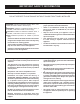
MANTLE AND TRIM CLEARANCES COMBUSTIBLE MANTEL/TRIM AREA 12” A B C D E F G H I J K L M N P O Q R S T V 8” U W X Z Y MINIMUM CLEARANCE TO PERPENDICULAR COMBUSTIBLE SIDE-WALL (FROM EDGE OF DOOR FRAME) TOP OF INSERT Figure 3 SURROUND PANELS Distance from Face of Fireplace Height Above Top of Insert A 10” N 23” B 9-1/4” O 22” C 8-3/4” P 21” D 8” Q 20” E 7-1/4” R 19” F 6-1/2” S 18” G 6” T 17” H 5-1/4” U 16” I 4-1/2” V 15” J 3-3/4” W 14” K 3” X 13” L 2-1/2”
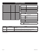
GAS SUPPLY The gas pipeline can be brought in through the right or left side of the appliance. The insert has a Flexline with shutoff valve located on the right side when facing the unit. See Figures 5 and 6. Consult the current National Fuel Gas Code, ANSI Z223.1 CAN/CGA-B149 (.1 or .2) installation code. Recommended Gas Pipe Diameter Pipe Length Schedule 40 Pipe Inside Diameter Tubing, Type L Outside Diameter Nat. L.P. Nat. L.P. 0-10ft 0-3m 1/2" 12.7mm 3/8" 9.5mm 1/2" 12.7mm 3/8" 9.
VENTING AND INSTALLATION 1. 2. To begin, remove the glass door from the unit. Note: The glass door assembly is secured to the firebox with two (2) spring clamps at the top of the door, and two (2) spring clamps at the bottom of the door. Check to make sure there is no hidden damage to the unit. Take a minute and plan out the gas, venting and electrical route. It is best to start with the gas line first, followed by the chimney liner and electrical supply requirements.
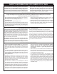
VENTING AND INSTALLATION Vent System Approvals Figure 8 shows the vent termination caps and systems approved for use with these models. Approved vent system terminations are labeled for identification. 3-inch diameter listed flexible aluminum or stainless steel gas vent is used for both the incoming combustion air and exhaust vent pipes. NO OTHER VENTING SYSTEMS OR COMPONENTS MAY BE USED.
VENTING AND INSTALLATION RECTANGULAR TERMINATION CAP (DVVK3FV KIT) ROUND TERMINATION CAP (DVKI KIT) ROUND CO-LINEAR TO CO-AXIAL ADAPTOR INTAKE VENT 10’ MINIMUM 35’ MAXIMUM FLUE EXHAUST VENT VENT CLAMPS OPTIONAL LOW VOLTAGE WIRES BLOWER ACCESS COVER PLATE OPTIONAL ON/OFF SWITCH LOCATION BLOWER POWER CORD Figure 8 Page 12 29209-0-0911
VERTICAL TERMINATION Determining Minimum Vent Height Above the Roof. WARNING Major U.S. building codes specify minimum chimney and/or vent height above the roof top. These minimum heights are necessary in the interest of safety. These specifications are summarized in Figure 9. Vertical Through the Roof Applications The Gas Fireplace Insert has been approved for: a) Vertical installations up to 35 feet in height (top of insert to cap).
ALTERNATE ON/OFF SWITCH INSTALLATION WIRING THE FIREPLACE 6. NOTICE: Electrical wiring must be installed by a licensed electrician. CAUTION DISCONNECT REMOTE CONTROLS IF YOU ARE ABSENT FOR EXTENDED TIME PERIODS. THIS WILL PREVENT ACCIDENTAL FIREPLACE OPERATION. Attach the surround panel assembly to the insert. Hang the surround panel assembly on the face of the insert and center left to right. Swing the surround panel assembly inward until the bottom magnets contact the insert body side flanges.
SURROUND PANEL INSTALLATION INSTALLING THE TRIM SURROUNDS Combustible materials MUST NEVER overlap onto the front face. WARNING WHEN FINISHING THE FIREPLACE INSERT, NEVER OBSTRUCT OR MODIFY THE AIR INLET/OUTLET LOUVERS ON THE FIREPLACE INSERT IN ANY MANNER. 1” Ref.
BLOWER ACCESSORY INFORMATION The appliance, when installed must be electrically connected and grounded in accordance with local codes or, in the absence of local codes, with the current CSA C22.1 Canadian Electrical Code. U.S. Installations, follow local codes and the National Electrical Code, ANSI/NFPA No. 70. Should this blower require servicing, the power supply must be disconnected. For rewiring of any replacement components, refer to Figures 16 and 17 and the parts list on pages 30-31.
OPTIONAL DECORATIVE GLASS PLACEMENT WARNING: Failure to position the parts in accordance with the diagrams and instructions below or failure to use only parts specifically approved for use with this heater may result in property damage or personal injury. NOTE: The DVL Fireplace Insert may be operated with or without the Decorative glass accessory options. Follow the directions below should you choose to enhance your Loft Fireplace Insert with any one of the available decorative glass options.
MILLIVOLT OPERATING INSTRUCTIONS 750 Millivolt System The standing pilot (750 millivolt system) is a continuous burning pilot. The pilot remains ON even when the main burner is OFF. The OWNER should carefully read and follow these operating instructions at all times. Lower the door assembly to view the gas controls for the fireplace. When you ignite the pilot, the thermopile produces millivolts (electrical current) which energizes the magnet in the gas valve.
STANDING PILOT LIGHTING INSTRUCTIONS FOR YOUR SAFETY READ BEFORE LIGHTING WARNING: If you do not follow these instructions exactly, a fire or explosion may result causing property damage, personal injury or loss of life. A. This appliance has a pilot which must be lighted by hand. When lighting the pilot, follow these instructions exactly. B. Before lighting smell all around the appliance area for gas. Be sure to smell next to the floor because some gas is heavier than air and will settle on the floor.
STANDING PILOT WIRING For Standing Pilot Ignition Wiring Optional Wall Switch Appliance Requirements Position the wall switch in the desired position on a wall. Run a maximum of 25 feet (7.8m) or less length of 18 A.W.G. minimum wire and connect it to the fireplace valve pigtails. WARNING DO NOT CONNECT 110-120 VAC TO THE GAS CONTROL VALVE OR THE APPLIANCE WILL MALFUNCTION AND THE VALVE WILL BE DESTROYED. WARNING DO NOT CONNECT THE 110-120 VAC TO THE WALL SWITCH OR THE CONTROL VALVE WILL BE DESTROYED.
STANDING PILOT TROUBLESHOOTING With proper installation and maintenance, your new Direct Vent Gas Fireplace will provide years of trouble-free service. If you do experience a problem, refer to the Trouble Shooting Guide below. This guide will assist a qualified service person in the diagnosis of problems and the corrective action to be taken. 1. 2. 3. Spark ignitor will not light pilot after repeated triggering of piezo ignitor button. a.
IPI ELECTRONIC SYSTEM OPERATING INSTRUCTIONS Attention: For shipping purposes, the Electronic Control Module and Receiver Plate assembly is loosely packaged near the left side of the appliance. It is necessary that the receiver plate assembly be secured to the left front flange of the appliance at the time of installation.
IPI ELECTRONIC SYSTEM WIRING DIAGRAM BLUE BLUE WHITE WHITE GREEN ( CPI/IPI SWITCH ORANGE ON/OFF SWITCH REMOTE RECEIVER OR (OPTIONAL) PILOT YELLOW WHITE + ON REMOTE - OFF ORANGE BLACK WHITE GAS CONTROL VALVE (GND) WHITE ( GREEN ( BLACK AC/DC POWER ADAPTOR RED BATTERY BLACK BACK-UP RED ELECTRONIC CONTROL MODULE BATTERY HOLDER If any of the original wire as supplied with this unit must be replaced, it must be replaced with equivalent gauge and temperature rated wire.
INTERMITTENT PILOT LIGHTING INSTRUCTIONS FOR YOUR SAFETY READ BEFORE LIGHTING WARNING: If you do not follow these instructions exactly, a fire or explosion may result causing property damage, personal injury or loss of life. A. This appliance has a pilot which must be lighted by hand. When lighting the pilot, follow these instructions exactly. B. Before lighting smell all around the appliance area for gas. Be sure to smell next to the floor because some gas is heavier than air and will settle on the floor.
INTERMITTENT CONTROL SYSTEM TROUBLESHOOTING Brief Description of the Components The gas valve is fitted with a manual HI/LO knob to allow for manual modulation of the gas outlet pressure to the appliance burner. The controls are designed to be used with either LPG or Natural Gas and can be converted by use of an OEM supplied conversion kit. The Digital Fireplace Control (DFC) is an automatic gas ignition system based on a single microcontroller core.
INTERMITTENT CONTROL SYSTEM TROUBLESHOOTING 1 If the DFC giving signal lock out: The board should be unlocked to reinitiate a pilot flame ignition (for the correct unlock sequence refer to the DFC Use and Installation Instructions). NO Is the DFC board in lock out? NO 1. Verify the electrical connections’ integrity and make sure they are in accordance with the relevant system wiring diagram. If necessary replace the wire harness. 2. Replace the DFC board. YES 1.
INTERMITTENT CONTROL SYSTEM TROUBLESHOOTING 2 Main burner lights when the pilot only should light. 1. Replace DFC board. 2. Replace the gas valve. YES 1. Verify the pilot flame fully engulfs the tip of the sense electrode. If not replace the pilot assembly. NO 2. Replace the pilot assembly. 3. Carefully clean the electrical connections of the sense cable, and the DFC board sense cable connection. Pilot holds the flame?. NO 4.
INSERT MAINTENANCE AND SERVICE Although the frequency of servicing and maintenance will depend on use and the type of installation, you should have a qualified service technician perform an appliance checkup at the beginning of each heating season. Specific guidelines regarding each appliance maintenance task are listed below. Cleaning IMPORTANT: TURN OFF THE GAS BEFORE SERVICING YOUR APPLIANCE. Frequency: After the first 3 to 4 hours of use. As necessary after initial cleaning.
ACCESSORIES The following accessory parts can be obtained from your Empire Comfort Systems dealer. If you need additional information beyond what your dealer can furnish, contact Empire Comfort Systems Inc., Nine Eighteen Freeburg Ave., Belleville, Illinois 62220.
INSERT PARTS VIEW 1 1 2 3 37 36 39 4 4 35 34 5 40 8 7 33 32 9 10 7 12 11 13 20 16 19 18 17 15 14 22 42 21 22 45 25 41 23 28 24 43 6 27 4 4 26 38 47 29 31 44 46 30 INSERT PARTS LIST PART NUMBER INDEX NO.
INSERT PARTS LIST PART NUMBER INDEX NO.
MASTER PARTS DISTRIBUTOR LIST To Order Parts Under Warranty, please contact your local Empire dealer. See the dealer locator at www.empirecomfort. com. To provide warranty service, your dealer will need your name and address, purchase date and serial number, and the nature of the problem with the unit. To Order Parts After the Warranty Period, please contact your dealer or one of the Master Parts Distributors listed below. This list changes from time to time.
APPLIANCE SERVICE HISTORY Date Dealer Name 29209-0-0911 Service Technician Name Service Performed/Notes Page 33
APPLIANCE SERVICE HISTORY Date Page 34 Dealer Name Service Technician Name Service Performed/Notes 29209-0-0911
APPLIANCE SERVICE HISTORY Date Dealer Name 29209-0-0911 Service Technician Name Service Performed/Notes Page 35
EMPIRE Comfort Systems Empire Comfort Systems Inc. 918 Freeburg Ave. Belleville, IL 62220 If you have a general question about our products, please e-mail us at info@empirecomfort.com. If you have a service or repair question, please contact your dealer. www.empirecomfort.