
Operation Manual


- 4 -
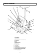
PARTS DIAGRAM
1. Thread pole
2. Spool pin
3. Spool holder
4. Lower looper thread tension dial
5. Handwheel
6. Base
7. Machine socket
8. Power switch
9. Front cover
10. Support bed
11. Free arm
12. Needle plate
13. Upper looper thread tension dial
14. Left needle thread tension dial
15. Right needle thread tension dial
16. Thread guide plate
4
2
3
5
6
7
8
9
10
11
12
13
16
14
15
1