3rd rvw Draft as of: 29 January, 2020 Honeywell International Inc. 400 Maple Grove Road Ottawa, Ontario K2V 1B8 Canada CAGE: 38473 Telephone: 800-601-3099 (Toll Free U.S.A./Canada) Telephone: 602-365-3099 (International Direct) Website: www.myaerospace.com System Description, Installation, and Maintenance Manual T ASPIRE-400 Model ASPIRE 400 HPA ASPIRE 400 SDU ASPIRE 400 SCM D R AF Part Number 90404514-000 90402651-000 90402652-000 Legal Notice Export Control These items are controlled by the U.S.
3rd rvw Draft as of: 29 January, 2020 SYSTEM DESCRIPTION, INSTALLATION, AND MAINTENANCE MANUAL ASPIRE-400 Proprietary Information Honeywell - Confidential COPYRIGHT BY HONEYWELL INTERNATIONAL INC. (“HONEYWELL”). ALL RIGHTS RESERVED. THIS DOCUMENT AND ALL INFORMATION CONTAINED HEREIN ARE THE CONFIDENTIAL AND PROPRIETARY INFORMATION OF HONEYWELL AND CONTAIN HONEYWELL TRADE SECRETS.
rd rvw Draft as of: 29 January, 2020 SYSTEM DESCRIPTION, INSTALLATION, AND MAINTENANCE MANUAL ASPIRE-400 agree that Materials shall only be used for the purpose of the rights granted herein. The Material furnished hereunder may be subject to U.S. export regulations. You will adhere to all U.S. export regulations as published and released from time to time by the U.S. Government.
3rd rvw Draft as of: 29 January, 2020 SYSTEM DESCRIPTION, INSTALLATION, AND MAINTENANCE MANUAL ASPIRE-400 HONEYWELL BE LIABLE FOR ANY INCIDENTAL DAMAGES, CONSEQUENTIAL DAMAGES, SPECIAL DAMAGES, INDIRECT DAMAGES, LOSS OF PROFITS, LOSS OF REVENUES, OR LOSS OF USE, EVEN IF INFORMED OF THE POSSIBILITY OF SUCH DAMAGES.
3rd rvw Draft as of: 29 January, 2020 SYSTEM DESCRIPTION, INSTALLATION, AND MAINTENANCE MANUAL ASPIRE-400 Copyright - Notice Copyright 2019 Honeywell International Inc. All rights reserved. Honeywell is a registered trademark of Honeywell International Inc. D R AF T All other marks are owned by their respective companies. 23-15-49 © Honeywell International Inc. Do not copy without express permission of Honeywell.
3rd rvw Draft as of: 29 January, 2020 R AF T SYSTEM DESCRIPTION, INSTALLATION, AND MAINTENANCE MANUAL ASPIRE-400 D Blank Page 23-15-49 © Honeywell International Inc. Do not copy without express permission of Honeywell.
3rd rvw Draft as of: 29 January, 2020 SYSTEM DESCRIPTION, INSTALLATION, AND MAINTENANCE MANUAL ASPIRE-400 TRANSMITTAL INFORMATION TO HOLDERS OF ASPIRE-400 SDIM, ATA NO. 23-15-49 (PUB. NO. D201902000020), ISSUED FOR USE IN SUPPORT OF THE FOLLOWING: Table TI-1 shows the applicable components. Table TI-1.
3rd rvw Draft as of: 29 January, 2020 R AF T SYSTEM DESCRIPTION, INSTALLATION, AND MAINTENANCE MANUAL ASPIRE-400 D Blank Page EFFECTIVITY ALL 23-15-49 © Honeywell International Inc. Do not copy without express permission of Honeywell.
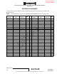
3rd rvw Draft as of: 29 January, 2020 SYSTEM DESCRIPTION, INSTALLATION, AND MAINTENANCE MANUAL ASPIRE-400 RECORD OF REVISIONS For each revision, write the revision number, revision date, date put in the manual, and your initials in the applicable column. NOTE: Refer to the Revision History in the TRANSMITTAL INFORMATION section for revision data.
3rd rvw Draft as of: 29 January, 2020 R AF T SYSTEM DESCRIPTION, INSTALLATION, AND MAINTENANCE MANUAL ASPIRE-400 D Blank Page EFFECTIVITY ALL 23-15-49 © Honeywell International Inc. Do not copy without express permission of Honeywell.
3rd rvw Draft as of: 29 January, 2020 SYSTEM DESCRIPTION, INSTALLATION, AND MAINTENANCE MANUAL ASPIRE-400 RECORD OF TEMPORARY REVISIONS Instructions on each page of a temporary revision tell you where to put the pages in your manual. Remove the temporary revision pages only when discard instructions are given. For each temporary revision, put the applicable data in the record columns on this page. Definition of Status column: A TR may be active, incorporated, or deleted.
3rd rvw Draft as of: 29 January, 2020 R AF T SYSTEM DESCRIPTION, INSTALLATION, AND MAINTENANCE MANUAL ASPIRE-400 D Blank Page EFFECTIVITY ALL 23-15-49 © Honeywell International Inc. Do not copy without express permission of Honeywell.
3rd rvw Draft as of: 29 January, 2020 SYSTEM DESCRIPTION, INSTALLATION, AND MAINTENANCE MANUAL ASPIRE-400 SERVICE BULLETIN LIST Title Modification Date Put In Manual D R AF T Service Bulletin / Revision Number EFFECTIVITY ALL 23-15-49 © Honeywell International Inc. Do not copy without express permission of Honeywell.
3rd rvw Draft as of: 29 January, 2020 R AF T SYSTEM DESCRIPTION, INSTALLATION, AND MAINTENANCE MANUAL ASPIRE-400 D Blank Page EFFECTIVITY ALL 23-15-49 © Honeywell International Inc. Do not copy without express permission of Honeywell.
3rd rvw Draft as of: 29 January, 2020 SYSTEM DESCRIPTION, INSTALLATION, AND MAINTENANCE MANUAL ASPIRE-400 LIST OF EFFECTIVE PAGES Subheading and Page Date Subheading and Page Title Date TOC-5 22 Apr 2019 T-1 22 Apr 2019 TOC-6 22 Apr 2019 T-2 22 Apr 2019 TOC-7 22 Apr 2019 T-3 22 Apr 2019 TOC-8 22 Apr 2019 T-4 22 Apr 2019 TOC-9 22 Apr 2019 T-5 22 Apr 2019 TOC-10 22 Apr 2019 T-6 22 Apr 2019 TOC-11 22 Apr 2019 TOC-12 22 Apr 2019 Transmittal Information TI-2 22 Apr 2019 Intro
3rd rvw Draft as of: 29 January, 2020 SYSTEM DESCRIPTION, INSTALLATION, AND MAINTENANCE MANUAL ASPIRE-400 LIST OF EFFECTIVE PAGES (Cont) Subheading and Page Date Subheading and Page Date 22 Apr 2019 2-18 22 Apr 2019 1-12 22 Apr 2019 2-19 22 Apr 2019 1-13 22 Apr 2019 2-20 22 Apr 2019 1-14 22 Apr 2019 2-21 22 Apr 2019 1-15 22 Apr 2019 2-22 22 Apr 2019 1-16 22 Apr 2019 2-23 22 Apr 2019 1-17 22 Apr 2019 2-24 22 Apr 2019 1-18 22 Apr 2019 2-25 22 Apr 2019 1-19 22 Apr 2019 2-2
3rd rvw Draft as of: 29 January, 2020 SYSTEM DESCRIPTION, INSTALLATION, AND MAINTENANCE MANUAL ASPIRE-400 LIST OF EFFECTIVE PAGES (Cont) Subheading and Page Date Subheading and Page Date 3-3 22 Apr 2019 F 4-37/4-38 22 Apr 2019 3-4 22 Apr 2019 F 4-39/4-40 22 Apr 2019 3-5 22 Apr 2019 F 4-41/4-42 22 Apr 2019 3-6 22 Apr 2019 F 4-43/4-44 22 Apr 2019 4-45 22 Apr 2019 4-46 22 Apr 2019 Section 4 INSTALLATION 4-1 22 Apr 2019 4-2 22 Apr 2019 F 4-3/4-4 22 Apr 2019 5-1 22 Apr 2019
3rd rvw Draft as of: 29 January, 2020 SYSTEM DESCRIPTION, INSTALLATION, AND MAINTENANCE MANUAL ASPIRE-400 LIST OF EFFECTIVE PAGES (Cont) Subheading and Page Date Subheading and Page Date 5-24 22 Apr 2019 5-55 22 Apr 2019 5-25 22 Apr 2019 5-56 22 Apr 2019 5-26 22 Apr 2019 5-57 22 Apr 2019 5-27 22 Apr 2019 5-58 22 Apr 2019 5-28 22 Apr 2019 5-29 22 Apr 2019 5-30 22 Apr 2019 5-31 22 Apr 2019 5-32 22 Apr 2019 5-33 22 Apr 2019 5-34 22 Apr 2019 5-35 22 Apr 2019 5-38 5-39 5-40 5
3rd rvw Draft as of: 29 January, 2020 SYSTEM DESCRIPTION, INSTALLATION, AND MAINTENANCE MANUAL ASPIRE-400 LIST OF EFFECTIVE PAGES (Cont) Subheading and Page Date Subheading and Page Date 6-26 22 Apr 2019 A-11 22 Apr 2019 6-27 22 Apr 2019 A-12 22 Apr 2019 6-28 22 Apr 2019 Section 7 TROUBLESHOOTING 22 Apr 2019 7-2 22 Apr 2019 7-3 22 Apr 2019 7-4 22 Apr 2019 7-5 22 Apr 2019 7-6 22 Apr 2019 7-7 22 Apr 2019 7-8 22 Apr 2019 R AF T 7-1 7-9 22 Apr 2019 7-10 22 Apr 2019 7-11 22
3rd rvw Draft as of: 29 January, 2020 R AF T SYSTEM DESCRIPTION, INSTALLATION, AND MAINTENANCE MANUAL ASPIRE-400 D Blank Page EFFECTIVITY ALL 23-15-49 © Honeywell International Inc. Do not copy without express permission of Honeywell.
3rd rvw Draft as of: 29 January, 2020 SYSTEM DESCRIPTION, INSTALLATION, AND MAINTENANCE MANUAL ASPIRE-400 TABLE OF CONTENTS LIST OF SECTIONS Title Page D R AF T INTRODUCTION ............................................................................................................................... INTRO-1 1 How to Use This Manual .......................................................................................................... INTRO-1 A General ..............................................
3rd rvw Draft as of: 29 January, 2020 SYSTEM DESCRIPTION, INSTALLATION, AND MAINTENANCE MANUAL ASPIRE-400 TABLE OF CONTENTS (Continued) LIST OF SECTIONS Title Page D R AF T 4 Tx RF Modes of Operation ................................................................................................................2-4 A General ...................................................................................................................................2-4 5 Tx In-band (L-band) Performance ...........
3rd rvw Draft as of: 29 January, 2020 SYSTEM DESCRIPTION, INSTALLATION, AND MAINTENANCE MANUAL ASPIRE-400 TABLE OF CONTENTS (Continued) LIST OF SECTIONS Title 16 17 T 15 B Air to Ground - Call Direction ..................................................................................................2-30 C Connected and Release .........................................................................................................2-30 D 4-Wire Call Control .............................................
3rd rvw Draft as of: 29 January, 2020 SYSTEM DESCRIPTION, INSTALLATION, AND MAINTENANCE MANUAL ASPIRE-400 TABLE OF CONTENTS (Continued) LIST OF SECTIONS Title 3 4 B HPA Installation .....................................................................................................................4-15 C SCM Installation ....................................................................................................................4-15 D SDU Installation .............................................
3rd rvw Draft as of: 29 January, 2020 SYSTEM DESCRIPTION, INSTALLATION, AND MAINTENANCE MANUAL ASPIRE-400 TABLE OF CONTENTS (Continued) LIST OF SECTIONS Title Page D R AF T A APP Boot ..............................................................................................................................5-10 B APP Control ..........................................................................................................................5-10 C APP Application Start up .......................
3rd rvw Draft as of: 29 January, 2020 SYSTEM DESCRIPTION, INSTALLATION, AND MAINTENANCE MANUAL ASPIRE-400 TABLE OF CONTENTS (Continued) LIST OF SECTIONS Title Page A B C D E F G H I J K L M IRS1 Interface ("Data from Primary IRS/GNSS") ......................................................................5-41 IRS2 Interface ("Data from Secondary IRS/GNSS") ..................................................................5-43 GNSS Interface ("Data from GNSS to SDU") ......................................
3rd rvw Draft as of: 29 January, 2020 SYSTEM DESCRIPTION, INSTALLATION, AND MAINTENANCE MANUAL ASPIRE-400 TABLE OF CONTENTS (Continued) LIST OF SECTIONS Title Page D R AF T K SDU POST Monitoring ...........................................................................................................6-18 L SATCOM POST Monitoring ....................................................................................................6-20 M Continuous Fault and Event Monitoring .............................
3rd rvw Draft as of: 29 January, 2020 SYSTEM DESCRIPTION, INSTALLATION, AND MAINTENANCE MANUAL ASPIRE-400 TABLE OF CONTENTS (Continued) LIST OF SECTIONS Title Page D R AF T C Federal Communication Commission ....................................................................................... A-3 D Industry Canada ..................................................................................................................... A-3 E European Technical Standards Institute (ETSI) ..................
3rd rvw Draft as of: 29 January, 2020 SYSTEM DESCRIPTION, INSTALLATION, AND MAINTENANCE MANUAL ASPIRE-400 TABLE OF CONTENTS (Continued) LIST OF FIGURES Description Figure Page Symbols................................................................................................................... INTRO-2 1-1 1-2 Aspire 400 System Diagram ...............................................................................................1-2 High Power Amplifier (HPA) Block diagram .........................
3rd rvw Draft as of: 29 January, 2020 SYSTEM DESCRIPTION, INSTALLATION, AND MAINTENANCE MANUAL ASPIRE-400 TABLE OF CONTENTS (Continued) Table LIST OF TABLES Description Page Aspire 400 Component Part Numbers ........................................................................ INTRO-2 INTRO-2 1-1 List of Acronyms and Abbreviations............................................................................ INTRO-4 Aspire 400 Component Part Numbers ....................................................
3rd rvw Draft as of: 29 January, 2020 SYSTEM DESCRIPTION, INSTALLATION, AND MAINTENANCE MANUAL ASPIRE-400 TABLE OF CONTENTS (Continued) LIST OF TABLES Description Table Page Priority "SATCOM System State" Description.......................................................................7-4 Priority "Non-Safety Logon State" Description ......................................................................7-5 A-1 Environmental Conditions and Test Procedures ..............................................
3rd rvw Draft as of: 29 January, 2020 R AF T SYSTEM DESCRIPTION, INSTALLATION, AND MAINTENANCE MANUAL ASPIRE-400 D Blank Page EFFECTIVITY ALL 23-15-49 © Honeywell International Inc. Do not copy without express permission of Honeywell.
3rd rvw Draft as of: 29 January, 2020 SYSTEM DESCRIPTION, INSTALLATION, AND MAINTENANCE MANUAL ASPIRE-400 INTRODUCTION How to Use This Manual General (1) This manual provides information about the installation of the Aspire 400 System. (2) Standard maintenance procedures that technicians must know are not given in this manual. (3) This publication is written in agreement with the ATA Specification. (4) Warnings, cautions, and notes in this manual give the data that follows: (5) B.
3rd rvw Draft as of: 29 January, 2020 SYSTEM DESCRIPTION, INSTALLATION, AND MAINTENANCE MANUAL ASPIRE-400 Figure INTRO-1. Symbols Units of Measure (1) F. Illustration (1) Supplemental illustrations use a suffix number to the basic figure number. For example, if Figure 501-5 is used, it signifies that it is an illustration of the item identified by index number 5 in Figure 501. (2) Illustrations with no specific designation are applicable to all units.
3rd rvw Draft as of: 29 January, 2020 SYSTEM DESCRIPTION, INSTALLATION, AND MAINTENANCE MANUAL ASPIRE-400 (c) Hardware part number controls FPGA firmware and micro-boot software components.
3rd rvw Draft as of: 29 January, 2020 SYSTEM DESCRIPTION, INSTALLATION, AND MAINTENANCE MANUAL ASPIRE-400 – IEEE Std 260.1, Standard Letter Symbols for Units of Measurement (available from the American National Standards Institute at http://www.ansi.org) – ASME Y14.38, Abbreviations for Use on Drawings and Related Documents (available from the American National Standards Institute at http://www.ansi. org) – ASME Y14.
3rd rvw Draft as of: 29 January, 2020 SYSTEM DESCRIPTION, INSTALLATION, AND MAINTENANCE MANUAL ASPIRE-400 Table INTRO-2.
3rd rvw Draft as of: 29 January, 2020 SYSTEM DESCRIPTION, INSTALLATION, AND MAINTENANCE MANUAL ASPIRE-400 Table INTRO-2.
3rd rvw Draft as of: 29 January, 2020 SYSTEM DESCRIPTION, INSTALLATION, AND MAINTENANCE MANUAL ASPIRE-400 Table INTRO-2.
3rd rvw Draft as of: 29 January, 2020 SYSTEM DESCRIPTION, INSTALLATION, AND MAINTENANCE MANUAL ASPIRE-400 Table INTRO-2.
3rd rvw Draft as of: 29 January, 2020 SYSTEM DESCRIPTION, INSTALLATION, AND MAINTENANCE MANUAL ASPIRE-400 Table INTRO-2.
3rd rvw Draft as of: 29 January, 2020 SYSTEM DESCRIPTION, INSTALLATION, AND MAINTENANCE MANUAL ASPIRE-400 Table INTRO-2. List of Acronyms and Abbreviations (Continued) Full Term SI International System of Units SPM standard practices manual SRU shop replaceable unit TCCA Transport Canada Civil Aviation TPOS test programs and operational software TR temporary revision TSDP technical support and data package TPA Transmit Pre-Amplifier U.S.A.
3rd rvw Draft as of: 29 January, 2020 SYSTEM DESCRIPTION, INSTALLATION, AND MAINTENANCE MANUAL ASPIRE-400 SECTION 1 – SYSTEM DESCRIPTION General Information (TASK 23-15-49) General B.
3rd rvw Draft as of: 29 January, 2020 T SYSTEM DESCRIPTION, INSTALLATION, AND MAINTENANCE MANUAL ASPIRE-400 D R AF Figure 1-1. Aspire 400 System Diagram EFFECTIVITY ALL 23-15-49 © Honeywell International Inc. Do not copy without express permission of Honeywell.
3rd rvw Draft as of: 29 January, 2020 SYSTEM DESCRIPTION, INSTALLATION, AND MAINTENANCE MANUAL ASPIRE-400 2. HPA Description (TASK 23-15-49) A. About High Power Amplifier (HPA) (1) The HPA provides high power amplification of the Transmitted (Tx) RF signal between the Satellite Data Unit and the antenna (via a DLNA). The HPA meets the ARINC 781 [ID4] functional requirements. (2) Table 1-2 provides the specifications for ASPIRE 400 HPA. Table 1-2.
3rd rvw Draft as of: 29 January, 2020 SYSTEM DESCRIPTION, INSTALLATION, AND MAINTENANCE MANUAL ASPIRE-400 (3) (a) L-band Tx RF Power Amplification (b) Processor RF Power Management and Diagnostics (c) Power Supply Secondary Power Generation and Management from Aircraft Primary Mains (d) Backplane - providing ARINC 600 [ID5] interface. The L-band Tx Power Amplification provides the primary function RF signal amplification.
3rd rvw Draft as of: 29 January, 2020 R AF T SYSTEM DESCRIPTION, INSTALLATION, AND MAINTENANCE MANUAL ASPIRE-400 D Figure 1-2. High Power Amplifier (HPA) Block diagram EFFECTIVITY ALL 23-15-49 © Honeywell International Inc. Do not copy without express permission of Honeywell.
3rd rvw Draft as of: 29 January, 2020 SYSTEM DESCRIPTION, INSTALLATION, AND MAINTENANCE MANUAL ASPIRE-400 (5) SDU System (TASK 23-15-49) B. Satellite Data Unit (1) The Aspire 400 Satellite Data Unit (SDU) is the central communications processing and control unit, largely determining the functionality of the complete Aircraft Earth Station.
3rd rvw Draft as of: 29 January, 2020 D R AF T SYSTEM DESCRIPTION, INSTALLATION, AND MAINTENANCE MANUAL ASPIRE-400 Figure 1-3. Aspire 400 Single Channel EFFECTIVITY ALL 23-15-49 © Honeywell International Inc. Do not copy without express permission of Honeywell.
3rd rvw Draft as of: 29 January, 2020 SYSTEM DESCRIPTION, INSTALLATION, AND MAINTENANCE MANUAL ASPIRE-400 NOTE: Application Mode: Dual Channel Aspire 400 ACD/AIS/PIES Configuration D R AF T D. The above diagram is a logical representation of the SDU functions and interconnections and does not imply a direct mapping to the physical implementation. EFFECTIVITY ALL 23-15-49 © Honeywell International Inc. Do not copy without express permission of Honeywell.
3rd rvw Draft as of: 29 January, 2020 D R AF T SYSTEM DESCRIPTION, INSTALLATION, AND MAINTENANCE MANUAL ASPIRE-400 Figure 1-4. Dual Channel Aspire 400 EFFECTIVITY ALL 23-15-49 © Honeywell International Inc. Do not copy without express permission of Honeywell.
3rd rvw Draft as of: 29 January, 2020 SYSTEM DESCRIPTION, INSTALLATION, AND MAINTENANCE MANUAL ASPIRE-400 NOTE: E. Figure 1-4 is a logical representation of the SDU functions and interconnections and does not imply a direct mapping to the physical implementation SDU System Characteristics (1) Table 1-3 provides the specifications for ASPIRE 400 SDU. Table 1-3. SDU Component Specifications Characteristic Specification SDU Part Number 90402651-000 Length 14.604 Inches (370.94 mm) MAX Width 2.
3rd rvw Draft as of: 29 January, 2020 SYSTEM DESCRIPTION, INSTALLATION, AND MAINTENANCE MANUAL ASPIRE-400 authentication. It assists in the replacement of faulty SDUs as it minimizes SDU configuration steps. B. (2) The USIM and Security Smart Card application reside on UICCs (Universal Integrated Circuit Card). Inmarsat has developed the applications and specifies the permissible devices which have the application loaded on them. (3) The SCM has no Complex Electronic devices.
3rd rvw Draft as of: 29 January, 2020 SYSTEM DESCRIPTION, INSTALLATION, AND MAINTENANCE MANUAL ASPIRE-400 Table 1-5.
3rd rvw Draft as of: 29 January, 2020 D R AF T SYSTEM DESCRIPTION, INSTALLATION, AND MAINTENANCE MANUAL ASPIRE-400 Figure 1-5. Inmarsat Communications Overview EFFECTIVITY ALL 23-15-49 © Honeywell International Inc. Do not copy without express permission of Honeywell.
3rd rvw Draft as of: 29 January, 2020 SYSTEM DESCRIPTION, INSTALLATION, AND MAINTENANCE MANUAL ASPIRE-400 The SATCOM Avionics Suite consists of two L-Band SATCOM systems. The left SATCOM system identified as SDU1 will operate on the Iridium network and the right SATCOM system identified as SDU2 will operate on the Inmarsat network. (4) Determination of the active and standby system is determined either by the crew or by an Aircraft algorithm outside the SATCOM.
3rd rvw Draft as of: 29 January, 2020 T SYSTEM DESCRIPTION, INSTALLATION, AND MAINTENANCE MANUAL ASPIRE-400 D R AF Figure 1-6. AES Class 6 System Configuration Showing 6F Sub-Class EFFECTIVITY ALL 23-15-49 © Honeywell International Inc. Do not copy without express permission of Honeywell.
3rd rvw Draft as of: 29 January, 2020 T SYSTEM DESCRIPTION, INSTALLATION, AND MAINTENANCE MANUAL ASPIRE-400 D R AF Figure 1-7. AES Class 7 System Configuration Showing 7F Sub-Class EFFECTIVITY ALL 23-15-49 © Honeywell International Inc. Do not copy without express permission of Honeywell.
3rd rvw Draft as of: 29 January, 2020 SYSTEM DESCRIPTION, INSTALLATION, AND MAINTENANCE MANUAL ASPIRE-400 Note the transmit high power amplifier function, and the RF diplexer function reside in different LRUs. (6) The external SCM contains the Secure Owner Requirements Table (ORT), the User Owner Requirements Table (ORT), two SwiftBroadband Universal Subscriber Identity Modules (USIMs) and the SBB Security Smartcard.
3rd rvw Draft as of: 29 January, 2020 SYSTEM DESCRIPTION, INSTALLATION, AND MAINTENANCE MANUAL ASPIRE-400 D R AF T Figure 1-8. Block Diagram of an AES6 and its Major Components EFFECTIVITY ALL 23-15-49 © Honeywell International Inc. Do not copy without express permission of Honeywell.
3rd rvw Draft as of: 29 January, 2020 SYSTEM DESCRIPTION, INSTALLATION, AND MAINTENANCE MANUAL ASPIRE-400 E. AES sub-class 7F (1) Due to this application being a sub-class 7F, no DLNA or HGA data will be provided. The modem in Figure 1-9 includes the function of the SDU and the SCM. D R AF T NOTE: EFFECTIVITY ALL 23-15-49 © Honeywell International Inc. Do not copy without express permission of Honeywell.
3rd rvw Draft as of: 29 January, 2020 SYSTEM DESCRIPTION, INSTALLATION, AND MAINTENANCE MANUAL ASPIRE-400 D R AF T Figure 1-9. Block Diagram of an AES7 and its Major System Components EFFECTIVITY ALL 23-15-49 © Honeywell International Inc. Do not copy without express permission of Honeywell.
3rd rvw Draft as of: 29 January, 2020 SYSTEM DESCRIPTION, INSTALLATION, AND MAINTENANCE MANUAL ASPIRE-400 Commonality Across Classes (1) The SDU, HPA and SCM are designed to support both classes of operation. The class of operation is determined by SDU configuration settings contained in a Secure Owner Requirement Table (ORT) File. (2) ORT files are used to identify aircraft specific configurations, and have a unique part number associated with each file created.
3rd rvw Draft as of: 29 January, 2020 R AF T SYSTEM DESCRIPTION, INSTALLATION, AND MAINTENANCE MANUAL ASPIRE-400 D Blank Page EFFECTIVITY ALL 23-15-49 © Honeywell International Inc. Do not copy without express permission of Honeywell.
3rd rvw Draft as of: 29 January, 2020 SYSTEM DESCRIPTION, INSTALLATION, AND MAINTENANCE MANUAL ASPIRE-400 SECTION 2 – SYSTEM OPERATION General A. System Overview (1) 2. The Aspire 400 SDU/SCM/HPA (Satellite Data Unit/ SDU Configuration Module/ High Power Amplifier) subsystem is part of the Aircraft Earth Station (AES) that facilitates airborne satellite communications using Swift Broadband (SBB) services over the Inmarsat L-Band satellite communications network. Modes of Operations A.
3rd rvw Draft as of: 29 January, 2020 D R AF T SYSTEM DESCRIPTION, INSTALLATION, AND MAINTENANCE MANUAL ASPIRE-400 Figure 2-1. Modes of Operation EFFECTIVITY ALL 23-15-49 © Honeywell International Inc. Do not copy without express permission of Honeywell.
3rd rvw Draft as of: 29 January, 2020 SYSTEM DESCRIPTION, INSTALLATION, AND MAINTENANCE MANUAL ASPIRE-400 RF Safe Mode (1) In RF Safe Mode, the RF output of the system is disabled because a significant system configuration problem has been detected. Safe Mode does permit other interactions with the equipment to allow the condition (e.g. loading a missing ORT) to be remedied. Even once the problem has been remedied, normal operation can only be achieved by a reset where the conditions are no longer present.
3rd rvw Draft as of: 29 January, 2020 SYSTEM DESCRIPTION, INSTALLATION, AND MAINTENANCE MANUAL ASPIRE-400 4. Tx RF Modes of Operation A. General Table 2-1. Tx RF Input/Output Tx Type Description dB(s) Tx RF Input VSWR The VSWR looking into the Tx RF interface does not exceed 1.5:1 when measured with respect to a characteristic impedance of 50 ohms anywhere within the L-band Tx frequency range.
3rd rvw Draft as of: 29 January, 2020 SYSTEM DESCRIPTION, INSTALLATION, AND MAINTENANCE MANUAL ASPIRE-400 Table 2-1. Tx RF Input/Output (Continued) Tx Type Description Tx RF Rated Output Power The HPA is capable of providing 64QAM maximum carrier-rated average power. Tx Output port +42.5 dBm +0.5 dB/-0 dB into a 50Î Ω load HPA Output port to Antenna RF port system loss of 2.
3rd rvw Draft as of: 29 January, 2020 SYSTEM DESCRIPTION, INSTALLATION, AND MAINTENANCE MANUAL ASPIRE-400 Table 2-2. Modulation Characteristics (Continued) Multiplier Modulation Roll-Off Factor Root raised cosine Symbol Rate Channel Bandwidth Nominated Bandwidth 2.5 32-QAM 0.13 84 ksym/s 94.92 kHz 100 kHz 5.0 32-QAM 0.13 168 ksym/s 189.8 kHz 200 kHz 2.5 64-QAM 0.13 84 ksym/s 94.92 kHz 100 kHz 5.0 64-QAM 0.13 168 ksym/s 189.
3rd rvw Draft as of: 29 January, 2020 SYSTEM DESCRIPTION, INSTALLATION, AND MAINTENANCE MANUAL ASPIRE-400 (f) E. Minimum of 1000 bursts. Tx EVM (1) Tx Spectral Regrowth G.
3rd rvw Draft as of: 29 January, 2020 SYSTEM DESCRIPTION, INSTALLATION, AND MAINTENANCE MANUAL ASPIRE-400 (c) (2) I. Tx output port referenced spurious and noise in the Tx-band, 1626.5 MHz to 1662.5 MHz while the PA is enabled and no carrier input is less than -56.5 dBm/3 kHz. NOTE: In Normal Operation the PA function will not be directed to disable PA function during periods of burst inactivity.
3rd rvw Draft as of: 29 January, 2020 SYSTEM DESCRIPTION, INSTALLATION, AND MAINTENANCE MANUAL ASPIRE-400 Table 2-3. Performance Limit for Expressed Modulation Type Sub-Band IM Order (min) Frequency (MHz) IM (dBc) Test Carriers Limiting Standard Below Rx Band 9 0.1 to 1518 -105 CW DO-210 Rx-band 7 1518 to 1559 -139 CW DO-210 GPS 5 1575.42 ± 12 -127.8 Modulated ETSI Glonass 3 1602 ±5.75 -112.8/500 Modulated ETSI 1605-1610 3 1605 to 1610 -112.
3rd rvw Draft as of: 29 January, 2020 SYSTEM DESCRIPTION, INSTALLATION, AND MAINTENANCE MANUAL ASPIRE-400 Table 2-4. Harmonic Frequency Range Harmonic dBm/Mhz Frequency Range 2nd -19.5 dBm/3 MHz 3253.0 MHz to 3321.0 MHz and 3336.0 MHz to 3350.0 MHz 3rd -29.5 dBm/3 MHz 4879.5 MHz to 4981.5 MHz and 5004.0 MHz to 5025.0 MHz 4th -29.5 dBm/3 MHz 6506 MHz to 6642 MHz and 6672.0 MHz to 6700.0 MHz 5th -29.5 dBm/3 MHz 8132.5 MHz to 8302.5 MHz and 8340.0 MHz to 8375.0 MHz 6th -40.
3rd rvw Draft as of: 29 January, 2020 SYSTEM DESCRIPTION, INSTALLATION, AND MAINTENANCE MANUAL ASPIRE-400 The HPA echos the existing condition of "PA Control" of the most recent ARINC-429 label 143 HPA Command word in the ARINC-429 label 143 HPA Status word of the current reporting interval when known else default with "Carrier Off" until assigned otherwise. (6) While in Normal Operating mode, the HPA achieves full transmit capability within 50 ms of the PA function being enabled.
3rd rvw Draft as of: 29 January, 2020 SYSTEM DESCRIPTION, INSTALLATION, AND MAINTENANCE MANUAL ASPIRE-400 "VSWR" OK/Unknown threshold status reported in ARINC-429 label 350 HPA Maintenance word (f) "Actual Power Out Status" status reported in label 143 HPA Status word.
3rd rvw Draft as of: 29 January, 2020 SYSTEM DESCRIPTION, INSTALLATION, AND MAINTENANCE MANUAL ASPIRE-400 (b) The numeric value to be conveyed is "Numeric Value" = ("computed average input level (dBm)" - (-45dBm)) / 0.1 dB (c) The numeric value is expressed as a 10-bit unsigned binary number.
3rd rvw Draft as of: 29 January, 2020 SYSTEM DESCRIPTION, INSTALLATION, AND MAINTENANCE MANUAL ASPIRE-400 (c) Forces a software reset. (7) The HPA continuously monitors the integrity of the software resident area of ROM.
3rd rvw Draft as of: 29 January, 2020 SYSTEM DESCRIPTION, INSTALLATION, AND MAINTENANCE MANUAL ASPIRE-400 While in "Normal Operation" state the receipt of an ARINC-429 label 143 HPA Command Word whose "Sign/Status Matrix" field is set to "Functional Test" evokes the execution of functional test provided the following conditions are satisfied: (a) The preceding ARINC-429 label 143 HPA Command word received "Sign/Status Matrix" field was set to "Normal Operation".
3rd rvw Draft as of: 29 January, 2020 SYSTEM DESCRIPTION, INSTALLATION, AND MAINTENANCE MANUAL ASPIRE-400 (b) Label 143 HPA Status word 2 Label 350 HPA Maintenance word 3 Label 357 Detector Data word.
3rd rvw Draft as of: 29 January, 2020 SYSTEM DESCRIPTION, INSTALLATION, AND MAINTENANCE MANUAL ASPIRE-400 (5) Recording the occurrence of deassertion to the Event log (c) Define "Command" as the state of indication of "Control Bus Input" of ARINC429 label 350 HPA Maintenance word for that and subsequent reporting intervals until asserted otherwise.
3rd rvw Draft as of: 29 January, 2020 SYSTEM DESCRIPTION, INSTALLATION, AND MAINTENANCE MANUAL ASPIRE-400 (2) B. (b) Providing a limited set of BITE tests that can only be performed by boot code. No other processors are active during this mode. This section describes the external hardware interfaces provided by the SDU. The presence of hardware interfaces in this section does not mean that these interfaces are supported by software or that they are functional in every mode of operation.
3rd rvw Draft as of: 29 January, 2020 SYSTEM DESCRIPTION, INSTALLATION, AND MAINTENANCE MANUAL ASPIRE-400 C. Low Public Public Emergency Satellite Logon Control and Display Functions (1) (2) (a) The satellite registration/logon status and control including selection of: (b) Log off (c) Auto logon (d) Constrained logon (e) Presence of a system failure that makes the SATCOM inoperable.
3rd rvw Draft as of: 29 January, 2020 SYSTEM DESCRIPTION, INSTALLATION, AND MAINTENANCE MANUAL ASPIRE-400 (1) (2) B. There are 2 anticipated mutually exclusive application configurations: Standalone and Dual Safety SATCOM. (a) Standalone: only one SDU. (b) Dual Safety SATCOM: 2 SDUs interconnected, but only one can be active and logged onto safety services at any one time. If the SDU Dual System Disable (DSD) discrete is asserted, the SDU: (a) Silently Logs off if already logged on.
3rd rvw Draft as of: 29 January, 2020 D R AF T SYSTEM DESCRIPTION, INSTALLATION, AND MAINTENANCE MANUAL ASPIRE-400 Figure 2-2. Dual SATCOM Standalone Configuration EFFECTIVITY ALL 23-15-49 © Honeywell International Inc. Do not copy without express permission of Honeywell.
3rd rvw Draft as of: 29 January, 2020 SYSTEM DESCRIPTION, INSTALLATION, AND MAINTENANCE MANUAL ASPIRE-400 NOTE: (2) The SDU enters Standalone Configuration if the ORT is configured for Standalone (3) When in Standalone Configuration, the ACD asserts its Dual System Select (DSS) discrete. Dual Safety SATCOM (Warm Standby) (1) When the ORT is configured for Dual Safety SATCOM, the SDU can be in an Active state or a Standby state. The SDU is only allowed to transmit when in the Active state.
3rd rvw Draft as of: 29 January, 2020 SYSTEM DESCRIPTION, INSTALLATION, AND MAINTENANCE MANUAL ASPIRE-400 Labels 272 and 274 on the "Data from MDCU 1, 2 or 3" interfaces. D R AF T (c) EFFECTIVITY ALL 23-15-49 © Honeywell International Inc. Do not copy without express permission of Honeywell.
3rd rvw Draft as of: 29 January, 2020 D R AF T SYSTEM DESCRIPTION, INSTALLATION, AND MAINTENANCE MANUAL ASPIRE-400 Figure 2-3. Dual SATCOM Dual Configuration EFFECTIVITY ALL 23-15-49 © Honeywell International Inc. Do not copy without express permission of Honeywell.
3rd rvw Draft as of: 29 January, 2020 SYSTEM DESCRIPTION, INSTALLATION, AND MAINTENANCE MANUAL ASPIRE-400 The SDU enters Standby state on start-up and stays in Standby state until commanded to go into Active State via Label 272 from the TCP when the following is true: 1 (e) (f) ORT configured for Aircraft Directed Dual Safety SATCOM. When all the following are true: 1 ORT configured for Aircraft Directed Dual Safety SATCOM.
3rd rvw Draft as of: 29 January, 2020 SYSTEM DESCRIPTION, INSTALLATION, AND MAINTENANCE MANUAL ASPIRE-400 Sets the SDU to Auto-Logon. 2 Automatically attempts to establish all ORT enabled services. When all the ORT is configured for Aircraft Directed Dual Safety SATCOM and the SDU considers itself "SDU in coverage": 1 The SDU sets bit 11 of Label 274 SATCOM OCA Interface Status to: a (m) Otherwise set it to 1 (n) 0.
3rd rvw Draft as of: 29 January, 2020 SYSTEM DESCRIPTION, INSTALLATION, AND MAINTENANCE MANUAL ASPIRE-400 (b) HW Name 11 characters (c) SDU Hardware Part Number 15 characters max (d) SDU Serial Number 15 characters max (e) Software Part Number(s): (f) 1 SDU Application 15 characters max 2 Secure ORT 15 characters max 3 User ORT 15 characters max. Software Part Names (designators). 1 SDU Application 15 characters max 2 Secure ORT 15 characters max 3 User ORT 15 characters max.
3rd rvw Draft as of: 29 January, 2020 SYSTEM DESCRIPTION, INSTALLATION, AND MAINTENANCE MANUAL ASPIRE-400 (13) (a) LRU Name 11 characters (b) Hardware Part Number 15 characters max (c) Serial Number 15 characters max (d) Name of SW application 15 characters max (e) Software Part Number 15 characters max. When ORT indicates the presence of the HPA, the ACD retrieves and maintains the following configuration information with characters limited to the maximum indicated.
3rd rvw Draft as of: 29 January, 2020 SYSTEM DESCRIPTION, INSTALLATION, AND MAINTENANCE MANUAL ASPIRE-400 (a) Return carrier activation (b) Sleep mode (c) Supplementary services (other than Call waiting, CLIP, CLIR and eMLPP as required for safety SBB voice) (d) G.
3rd rvw Draft as of: 29 January, 2020 SYSTEM DESCRIPTION, INSTALLATION, AND MAINTENANCE MANUAL ASPIRE-400 (b) (6) If a SBB capable satellite is removed from the System Information Broadcast, the ACD removes the satellite from its "Broadcast-updated Satellite Table". (7) The ACD replaces its non-volatile stored copy of the Satellite Table with the SCM ORT Satellite Table when the SCM ORT Satellite Table version differs from the previously SCM sourced ORT Satellite Table.
3rd rvw Draft as of: 29 January, 2020 SYSTEM DESCRIPTION, INSTALLATION, AND MAINTENANCE MANUAL ASPIRE-400 (b) (4) 1 Bit 26 if the call is on 4wire 1 2 Bit 27 if the call is on 4wire 2.
3rd rvw Draft as of: 29 January, 2020 D R AF T SYSTEM DESCRIPTION, INSTALLATION, AND MAINTENANCE MANUAL ASPIRE-400 Figure 2-4. (Sheet 1 of 2) Incoming PS Call Decision Logic EFFECTIVITY ALL 23-15-49 © Honeywell International Inc. Do not copy without express permission of Honeywell.
3rd rvw Draft as of: 29 January, 2020 D R AF T SYSTEM DESCRIPTION, INSTALLATION, AND MAINTENANCE MANUAL ASPIRE-400 Figure 2-4. (Sheet 2 of 2) Incoming PS Call Decision Logic EFFECTIVITY ALL 23-15-49 © Honeywell International Inc. Do not copy without express permission of Honeywell.
3rd rvw Draft as of: 29 January, 2020 SYSTEM DESCRIPTION, INSTALLATION, AND MAINTENANCE MANUAL ASPIRE-400 NOTE: (4) (5) The ACD routes or rejects an incoming PS safety voice SIP call (SIP:INVITE) according to the call decision logic defined by: (a) BGAN PS routing and preemption (b) Voice ORT configuration. The ACD PBX determines priority in Ground-to-Air VoIP calls from: (a) the SIP header Resource-priority field for VoIP calls if present, else, (b) set the call priority as Public.
3rd rvw Draft as of: 29 January, 2020 SYSTEM DESCRIPTION, INSTALLATION, AND MAINTENANCE MANUAL ASPIRE-400 (d) 1 ANSWER CALL command received from the Call display and control protocol 2 Associated Cockpit Voice Mic On discrete is in the on state. In Latched mode, the ACD connects the 4-wire Audio path for the mic: 1 From when the call is connected 2 Until the call is terminated.
3rd rvw Draft as of: 29 January, 2020 SYSTEM DESCRIPTION, INSTALLATION, AND MAINTENANCE MANUAL ASPIRE-400 (1) CS call setup messages are sent via the serial control link between them ACD and the Safety Channel Card. (2) CS voice data are sent via the serial voice link between the ACD and the Safety Channel Card. (3) The ACD PBX initiates CS Air-to-Ground calls by messaging the following to the safety Channel Card: (b) ICAO as the calling party number (c) Priority.
3rd rvw Draft as of: 29 January, 2020 SYSTEM DESCRIPTION, INSTALLATION, AND MAINTENANCE MANUAL ASPIRE-400 2 (3) (4) If an annunciated CS Ground-to-Air call is accepted, the ACD PBX: (a) Commands the Channel Card to accept the AMBE +2 call set up AND (b) When established connects the call through the Serial voice link to the routed 4wire port. When a CS Air-to-Ground call is connected, the ACD PBX connects the call through the Serial voice link to the routed 4-wire port.
3rd rvw Draft as of: 29 January, 2020 SYSTEM DESCRIPTION, INSTALLATION, AND MAINTENANCE MANUAL ASPIRE-400 (a) 14. Commands the safety Channel Card to terminate the Secondary context. Aircraft Information A. Navigation Information (1) Navigation information can come from multiple sources on a given aircraft including: (a) The Hybrid Inertial/GNSS Data source, the GNSS Data source and the Inertial Data source. One or more LRU can be providing the same type of data.
3rd rvw Draft as of: 29 January, 2020 SYSTEM DESCRIPTION, INSTALLATION, AND MAINTENANCE MANUAL ASPIRE-400 Table 2-6. Navigation Data (Continued) Description Priority Labels GNSS Sensor Status In some instances, these labels will not be available. 273 GNSS sensor status (2) There are no criteria on selecting a navigation solution when having 2 equal preference valid navigation solutions. Any method of selection is acceptable.
3rd rvw Draft as of: 29 January, 2020 SYSTEM DESCRIPTION, INSTALLATION, AND MAINTENANCE MANUAL ASPIRE-400 When the ORT indicates the external power amplifier supports cable calibration, the ACD automatically determines at an unspecified cable loss of between 0 to 18 dB, on a normal ground power on, storing its value in non-volatile memory for use under rapid restart condition. NOTE: The loss range indicated is at 1.6 GHz, but this does not imply that this 1.6 GHz is used for cable calibration.
3rd rvw Draft as of: 29 January, 2020 SYSTEM DESCRIPTION, INSTALLATION, AND MAINTENANCE MANUAL ASPIRE-400 (2) The ACARS Air-Ground Protocol (AAP) is Inmarsat's bespoke transport layer protocol used for tunneling of ACARS data over SwiftBroadband network. AAP version 2 defined in SDM Volume 3 Chapter 4 and in Iris Precursor System Design Document is to be implemented in the SDU by the Aircraft Data Link Gateway function (ADGW).
3rd rvw Draft as of: 29 January, 2020 SYSTEM DESCRIPTION, INSTALLATION, AND MAINTENANCE MANUAL ASPIRE-400 (a) The selected time and date has changed (b) The difference between internal time and date and selected time and date is greater than 10 seconds. NOTE: Checking for changing (non-static) data is to accommodate lab testing when the time label isn’t updating, i.e. labels continuously sent with same time and date.
3rd rvw Draft as of: 29 January, 2020 SYSTEM DESCRIPTION, INSTALLATION, AND MAINTENANCE MANUAL ASPIRE-400 Table 2-7.
3rd rvw Draft as of: 29 January, 2020 SYSTEM DESCRIPTION, INSTALLATION, AND MAINTENANCE MANUAL ASPIRE-400 (2) Based on the ORT, the ACD retrieves and set the ICAO from one of: (a) AES ID Input (Labels 275 & 276) (b) CMU (Labels 214 & 216) and enable the associated labels on the identified interface. (3) The first two valid and matching ICAO address labels received after power up on the ground is stored in non-volatile memory and used until the next on-ground power up.
3rd rvw Draft as of: 29 January, 2020 SYSTEM DESCRIPTION, INSTALLATION, AND MAINTENANCE MANUAL ASPIRE-400 SECTION 3 – SYSTEM PRE-CONFIGURATION Aircraft Information A. Flight Information (1) (a) Flight Phase (b) Flight Number (c) Aircraft ID (tail number), and sets the values to not available when CFDS labels are never received. Owner Requirements Table (ORT) A. Secure ORT (1) B. User ORT (1) (2) C.
3rd rvw Draft as of: 29 January, 2020 SYSTEM DESCRIPTION, INSTALLATION, AND MAINTENANCE MANUAL ASPIRE-400 (6) (a) AIS activation (b) 2nd channel activation (Side B of DABC, provides basic PIES service unless enhanced with additional PIES services). The Aspire 400 SDU supports permanent and expiring licensing of the following PIES features based on the features being ORT enabled: (a) PIES HDR (b) Router Capability.
3rd rvw Draft as of: 29 January, 2020 SYSTEM DESCRIPTION, INSTALLATION, AND MAINTENANCE MANUAL ASPIRE-400 (g) Minimum initial EIRP for Switft64 (A781 Ref E8): 1 (6) The ACD ensures that all ACD ORT parameters are assigned to the Secure ORT except for the following User ORT parameters: (a) SBB Service Provider APN (b) Cockpit Telephone Directory (c) Login Policy (d) Manual Dial Mode. (7) The AISD ensures that all AISD ORT parameters are assigned to the Secure ORT.
3rd rvw Draft as of: 29 January, 2020 SYSTEM DESCRIPTION, INSTALLATION, AND MAINTENANCE MANUAL ASPIRE-400 b Description. Safety Voice (1) (2) The ACD ensures the ORT contains the following parameters for SBB Safety Voice configuration: (a) APN (b) SIP Domain name. 4-wire Noise insertion (A781 Ref D6) applied to Classic voice, AMBE +2 codec provides its own specified noise insertion.
3rd rvw Draft as of: 29 January, 2020 SYSTEM DESCRIPTION, INSTALLATION, AND MAINTENANCE MANUAL ASPIRE-400 SDU codec #1 dedication (A781 Ref D1) always services cockpit voice. (c) Dual SATCOM Voice Channel Mapping. D R AF T (b) EFFECTIVITY ALL 23-15-49 © Honeywell International Inc. Do not copy without express permission of Honeywell.
3rd rvw Draft as of: 29 January, 2020 R AF T SYSTEM DESCRIPTION, INSTALLATION, AND MAINTENANCE MANUAL ASPIRE-400 D Blank Page EFFECTIVITY ALL 23-15-49 © Honeywell International Inc. Do not copy without express permission of Honeywell.
3rd rvw Draft as of: 29 January, 2020 SYSTEM DESCRIPTION, INSTALLATION, AND MAINTENANCE MANUAL ASPIRE-400 SECTION 4 – INSTALLATION Mechanical Installation (TASK 23-15-49) A. HPA/SDU Installation (1) B. The HPA and SDU are 2 MCU form compliant. They are for installation in an equipment rack, in close proximity to each other and with the expectation of external air cooling. RF and control between the SDU and the HPA is supported by dedicated interfaces.
3rd rvw Draft as of: 29 January, 2020 SYSTEM DESCRIPTION, INSTALLATION, AND MAINTENANCE MANUAL ASPIRE-400 "CAUTION: THIS UNIT IS NOT SUBJECT TO DAMAGE FROM ELECTROSTATIC DISCHARGE AS AN ASSEMBLY. HOWEVER, IT CONTAINS PARTS OR ASSEMBLIES THAT ARE SENSITIVE TO ELECTROSTATIC DISCHARGE." (b) The SDU and HPA have a label with a triangular Hot Surface Temperature warning symbol with bold upper case letters if any exposed part of the SDU surface exceeds the local ambient temperature by more than 15°C (59°F).
3rd rvw Draft as of: 29 January, 2020 D R AF T SYSTEM DESCRIPTION, INSTALLATION, AND MAINTENANCE MANUAL ASPIRE-400 Figure 4-1. (Sheet 1 of 3) HPA Outline and Installation EFFECTIVITY ALL 23-15-49 © Honeywell International Inc. Do not copy without express permission of Honeywell.
D R AF T 3rd rvw Draft as of: 29 January, 2020
3rd rvw Draft as of: 29 January, 2020 D R AF T SYSTEM DESCRIPTION, INSTALLATION, AND MAINTENANCE MANUAL ASPIRE-400 Figure 4-1. (Sheet 2 of 3) HPA Outline and Installation EFFECTIVITY ALL 23-15-49 © Honeywell International Inc. Do not copy without express permission of Honeywell.
D R AF T 3rd rvw Draft as of: 29 January, 2020
3rd rvw Draft as of: 29 January, 2020 D R AF T SYSTEM DESCRIPTION, INSTALLATION, AND MAINTENANCE MANUAL ASPIRE-400 Figure 4-1. (Sheet 3 of 3) HPA Outline and Installation EFFECTIVITY ALL 23-15-49 © Honeywell International Inc. Do not copy without express permission of Honeywell.
D R AF T 3rd rvw Draft as of: 29 January, 2020
3rd rvw Draft as of: 29 January, 2020 D R AF T SYSTEM DESCRIPTION, INSTALLATION, AND MAINTENANCE MANUAL ASPIRE-400 Figure 4-2. SCM Outline and Installation EFFECTIVITY ALL 23-15-49 © Honeywell International Inc. Do not copy without express permission of Honeywell.
D R AF T 3rd rvw Draft as of: 29 January, 2020
3rd rvw Draft as of: 29 January, 2020 D R AF T SYSTEM DESCRIPTION, INSTALLATION, AND MAINTENANCE MANUAL ASPIRE-400 Figure 4-3. (Sheet 1 of 2) SDU Outline and Installation EFFECTIVITY ALL 23-15-49 © Honeywell International Inc. Do not copy without express permission of Honeywell.
D R AF T 3rd rvw Draft as of: 29 January, 2020
3rd rvw Draft as of: 29 January, 2020 D R AF T SYSTEM DESCRIPTION, INSTALLATION, AND MAINTENANCE MANUAL ASPIRE-400 Figure 4-3. (Sheet 2 of 2) SDU Outline and Installation EFFECTIVITY ALL 23-15-49 © Honeywell International Inc. Do not copy without express permission of Honeywell.
D R AF T 3rd rvw Draft as of: 29 January, 2020
3rd rvw Draft as of: 29 January, 2020 SYSTEM DESCRIPTION, INSTALLATION, AND MAINTENANCE MANUAL ASPIRE-400 Electrical Installation (TASK 23-15-49) A. General (1) B. The Electrical System for the Aspire-400 consists of three main components, the HPA, SCM and SDU, with the SDU acting as a central hub for the other two. HPA Installation (1) Power Requirements (a) (2) C.
3rd rvw Draft as of: 29 January, 2020 D R AF T SYSTEM DESCRIPTION, INSTALLATION, AND MAINTENANCE MANUAL ASPIRE-400 Figure 4-4. ARINC 600 Receptacle with Index Pin Coding EFFECTIVITY ALL 23-15-49 © Honeywell International Inc. Do not copy without express permission of Honeywell.