
User's Manual


CI Wireless Inc.
1211 Ira E. Woods Ave., Grapevine, TX 76051
3
6.0
Identification of Hub
6.1
Front Panel Layout
6.2
Rear Panel Layout
6.3
Hub Components Layout
6.4
Optical Transceiver
6.5
Wave Division Multiplexer
6.6
System Interconnect
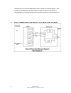
700-1005 Interconnect Module Board
Input Connectors
Controls
Terminal Strip
Attenuators
Output to Up Link Combiner RF Inputs
Input to Optical Transceiver RF Out
Other
700-1001 Board
7.0
Identification of Microcell
7.1
Left Panel, A Single Band
7.2
Left Panel, Dual Band
7.3
Door Panel Microcell
7.4
Back (Heat Sink) Microcell (EKO-8) (EKO 1.9R)
7.4b Back (Heat Sink) Microcell (EKO-1.9M)
7.5
Base Bottom
7.6
Triplexer
7.7
System Interconnect
8.0
Software Control Module
8.1
Microcell (Remote) Unit Controller
8.1.1
Basic Interface
8.1.2
System Setup
8.1.3
User Settings
8.1.4
Alarms
8.2
Hub Unit Controller
8.2.1
Basic Interface
8.2.2
System Setup
8.2.3
User Settings
8.2.4
Alarms
8.3
RS 232 Port Communications
8.3.1 Terminal Interface Displays
9.0
Installation
9.1
Introduction
9.2
Getting Started
9.3
Mounting Hub Hardware
9.4
Mounting the Microcell Unit