FCC Part 22 Transmitter Certification Test Report FCC ID: DNY0A1EKLNK800 FCC Rule Part: CFR 47 Part 22 Subpart H ACS Report Number: 05-0457-22H Manufacturer: EMS Wireless Equipment Type: Cellular Booster Remote Model: EkoLink II 800 Installation and Operators Guide 5015 B.U.
Operator’s Manual EkoLink II Fiber Optic Distributed Antenna System 608577-1 Rev A 2850 Colonnades Court Norcross, GA 30071 U. S. A. Tel: +1 770.582.
EMS Wireless EkoLink II Operator’s Manual Disclaimer Every attempt has been made to make this material complete, accurate, and up-to-date. Users are cautioned, however, that EMS Wireless reserves the right to make changes without notice and shall not be responsible for any damages, including consequential, caused by reliance on the material presented, including, but not limited to, typographical, arithmetical, or listing errors.
EMS Wireless EkoLink II Operator’s Manual Warnings, Cautions, and General Notes This product conforms to FCC Part 15, Section 21. Changes or modifications not expressly approved by the party responsible for compliance could void the user's authority to operate the equipment. FCC Class B: “NOTE: This equipment has been tested and found to comply with the limits for a Class B digital device, pursuant to Part 15 of the FCC Rules.
EMS Wireless EkoLink II Operator’s Manual Safety Considerations When installing or using this product, observe all safety precautions during handling and operation. Failure to comply with the following general safety precautions and with specific precautions described elsewhere in this manual violates the safety standards of the design, manufacture, and intended use of this product. EMS Wireless Inc. assumes no liability for the customer's failure to comply with these precautions.
EMS Wireless EkoLink II Operator’s Manual EMS Wireless Customer Support 2850 Colonnades Court Norcross, Georgia 30071 U. S. A. +1 (770) 582-0555 x5310 Service Do not attempt to modify or service any part of this product other than in accordance with procedures outlined in this Operator's Manual. If the product does not meet its warranted specifications, or if a problem is encountered that requires service, notify EMS Wireless's Customer Service Department.
EMS Wireless EkoLink II Operator’s Manual product which has been subject to alteration, abuse, improper installation or application, accident, electrical or environmental over-stress, negligence in use, storage, transportation, or handling. Specific Product Warranty Instructions All EMS Wireless products are manufactured to high quality standards and are warranted against defects in workmanship, materials and construction, and to no further extent.
EMS Wireless EkoLink II Operator’s Manual Repaired products are warranted for the balance of the original warranty period, or at least 90 days from date of shipment.
EMS Wireless EkoLink II Operator’s Manual Food and Drug Administration. This laser product complies with 21 CFR, Chapter I, Subchapter J of the DHEW standards under the Radiation Control for Health and Safety Act of 1968. The laser module certification label is located on the equipment enclosure and it also shows the required DANGER warning logotype (as shown below).
EMS Wireless EkoLink II Operator’s Manual DANGER INVISIBLE LASER RADIATION AVOID DIRECT EXPOSURE TO BEAM PEAK POWER 30 mW WAVELENGTH 1300/1550 nm CLASS IIIb LASER PRODUCT THIS PRODUCT COMPLIES WITH 21 CFR CHAPTER I SUBCHAPTER J 9
EMS Wireless EkoLink II Operator’s Manual TABLE OF CONTENTS 1.0 2.0 3.0 4.0 Introduction 1.1 System Overview 1.2 Functional Overview 1.2.1 Hub 1.2.2 Fiber 1.2.3 Remote 1.2.4 Antenna 1.2.5 Optional Components 1.2.5.1 AC Power Supply 1.2.5.2 DC Power Supply 1.2.5.3 RF Combiner Installation Guide 2.1 Shipment Contents 2.2 Available Options 2.3 Site Selection 2.3.1 Hubs 2.3.2 Remotes 2.4 Pre-Installation 2.5 Power Supply Installation 2.6 Single Hub Installation 2.7 Multiple Hub Installation 2.
EMS Wireless EkoLink II Operator’s Manual 4.7 4.8 5.0 Remote Specifications Alarm Output Specifications 4.8.1 Internal Alarms 4.8.2 External Alarms 4.8.2.1 Master Hub External Alarm Relays, J26 4.8.2.2 Master Hub External Alarm Relays, J27 Troubleshooting Guide 5.1 Remote Alarms 5.2 Hub Alarms 5.2.
EMS Wireless EkoLink II Operator’s Manual LIST OF FIGURES Figure 1: Typical EkoLink II Application Figure 2: EkoLink II Functional Diagram Figure 3: EkoLink II Hub Front Panel Figure 4: EkoLink II Hub Rear Panel Figure 5: EkoLink II Hub Rear Panel, Left Side Detail Figure 6: EkoLink II Hub Rear Panel, Right Side Detail Figure 7: EkoLink II Remote Unit Block Diagram Figure 8: EkoLink II Remote (Standard Enclosure Configuration) Figure 13: AC Power Supply Rear Panel Figure 14: DC Power Supply Rear Panel Fig
EMS Wireless EkoLink II Operator’s Manual Figure A-1: Connection Description in HyperTerminal Figure A-2: HyperTerminal Screen for Direct Connection Figure A-3: Port Settings for Direct Connection and Remote Connection 13
EMS Wireless EkoLink II Operator’s Manual LIST OF TABLES Table 1: Power per Carrier Table Table 2: Link Performance Specifications Table 3: User Requirement Specifications Table 4: EkoLink II Hub Specifications Table 5: EkoLink II AC Power Supply Specifications Table 6: EkoLink II DC Power Supply Specifications Table 7: RF Combiner Specifications Table 8: EkoLink II Remote Specifications Table 9: Hub Alarm Conditions Table 10: J26 Connector Table 11: J27 Connector Table 12: Remote Alarm Conditions Table 1
EMS Wireless EkoLink II Operator’s Manual 1.0 Introduction The system overview describes the need for distributed RF antenna systems in general terms and the concept of a fiber optic repeater system. The functional overview describes the EkoLink II system as it is broken down into its major components. 1.1 System Overview The EkoLink II System is designed to distribute Cellular and PCS radio signals within a building or campus of buildings where coverage/capacity would be otherwise impeded.
EMS Wireless EkoLink II Operator’s Manual EkoLink II system would be a multi-floor building such as the one depicted in Figure 1. In buildings of this type it is common to find equipment rooms for Heating, Ventilation and Air-Conditioning (HVAC) and other utilities such as data networking and telephony equipment. There are numerous advantages to centrally located utilities and services and cellular equipment is no exception.
EMS Wireless EkoLink II Operator’s Manual 1.2 Functional Overview There are four main components comprising the EkoLink II System: The Hub, the Remote, the Fiber, and the Antenna. Figure 2 is a functional diagram of the EkoLink II system. 1.2.1 Hub The Hub interfaces directly to the service provider’s BTS and is typically located in the equipment or utility room in most installations.
EMS Wireless EkoLink II Operator’s Manual Each EkoLink II Hub can support up to four Remotes. If more than four Remotes are required, up to 3 additional Hubs can be added allowing for a total of 16 Remotes. Front and rear views of the Hub unit are shown in Figures 3, 4, 5, and 6. Figure 3 shows the hub front panel with the uplink and downlink RF connectors (type N female), and the four fiber optic input/output connectors. Figure 4 shows the rear panel.
EMS Wireless EkoLink II Operator’s Manual Left side, detailed in Fig. 5 Right side, detailed in Fig. 6 Figure 4: EkoLink II Hub Rear Panel RJ11 modem connections for alarming DL RF connections to slave hub unit J26 relay alarm outputs, pin 1 on left; see Sect. 4.8.2 J27 collector alarm outputs, pin 1 on left; see Sect. 4.8.
EMS Wireless EkoLink II RF UL Connections for Slave Hub Operator’s Manual Data I/O for Slave Hubs DC Power Connection RS-232 Communications Port Figure 6: EkoLink II Hub Rear Panel, Right Side Detail 1.2.2 Fiber EMS recommends single mode 9/125 µm optical fiber for use in the EkoLink II system. It is also recommended that a high quality SC/APC connector be used to minimize reflections at the mating ends of the fiber. SC/APC connectors are standard on both the Remote and the Hub.
EMS Wireless EkoLink II Operator’s Manual The maximum fiber loss (including connectors) for EkoLink II is 5.0 dB. This correlates to roughly 10 km for a typical fiber such as Corning SMF-28. 1.2.3 Remote The remote is designed to convert the Fiber Optic Signals to/from RF and transmit those signals to/from the Hub. Figure 7 is a functional diagram of the EkoLink II remote.
EMS Wireless EkoLink II Operator’s Manual Figure 8: EkoLink II Remote (standard enclosure configuration). The Antenna port on each of the EkoLink II Remote enclosures is a standard 50 Ω, N-type connector. 1.2.4 Antenna The user supplied antenna is the final element in the EkoLink II system. Any number of antennas may be used so long as it is matched to 50 Ω. 1.2.5 Optional Components The components listed above are mandatory for any EkoLink II system deployment.
EMS Wireless EkoLink II Operator’s Manual 1.2.5.1 AC Power Supply There are two power supply offerings available from EMS Wireless which are specifically designed for deployment in EkoLink II systems. The AC Supply is shown in Figure 13. It has eight outputs for EkoLink II systems. Figure 13: AC Power Supply Rear Panel. 1.2.5.2 DC Power Supply In many telecommunications applications equipment is powered by 48 Volt DC power.
EMS Wireless EkoLink II Operator’s Manual 24 VDC input from BTS 48 VDC outputs for remotes Figure 14: DC Power Supply, Rear View Figure 15: DC Power Supply, Front View 24
EMS Wireless EkoLink II Operator’s Manual (+) 24 VDC Connection (+) 48 VDC Connection Figure 16: DC Power Supply, Cabling Detail 25
EMS Wireless EkoLink II Operator’s Manual Figure 17: DC Power Supply, Input and Output Connector Formats 1.2.5.3 RF Combiner The user desiring to accommodate more than one carrier in an EkoLink II system will require a combiner such as the one depicted in Figure 17.
EMS Wireless EkoLink II Operator’s Manual Figure 18: RF Combiner Rear Panel. The RF Combiner is installed at the Hub and accommodates two BTS inputs. 2.0 Installation Guide The following guidelines provide a step by step installation procedure which should be followed closely to insure a successful deployment. The photographs in Section 1 should be referred to frequently as the installation proceeds. 2.
EMS Wireless EkoLink II Operator’s Manual 2.3 Pre-installation Prior to installation, a carefully planned system layout should be documented. At a minimum, this document should include the location of the Hub, the location of the Remotes, the Antenna locations, the fiber locations and lengths, and the location of the power supplies for both Hubs and Remotes. The Hub is located at the Building Base Station or BTS. The Hub interfaces with the user's PCS System.
EMS Wireless EkoLink II (a) (b) (c) (d) Operator’s Manual RF power meter Optical power meter RF Spectrum analyzer Signal generator 2.4 Power Supply Installation If purchased, install the power supply and connect power to the Hub. The 120 VAC power supply has an on-off switch which is located on the rear of the chassis. This should remain in the off position until the installation is completed. 2.5 Single Hub Installation To Install the Hub, locate it as close as possible to the Service Provider’s BTS.
EMS Wireless EkoLink II Operator’s Manual 2.6 Multiple Hub Installation For installations requiring more than one Hub, there will be one Hub designated as the Master and the other Hubs will be slaved to the Master. Up to three additional Hubs can be slaved to a single Master Hub. The BTS will only interface to the Master Hub. An optional Master Alarm Controller may be purchased to allow alarms to be reported to an offsite monitoring station.
EMS Wireless EkoLink II Operator’s Manual • For external antenna use, connect the Antenna to the remote using 50 Ω cable with an N-type connector. • Remove the cover on the Remote fiber connector. Using a dust free air source, clean the fiber connector. • Remove the plastic cover on the fiber and clean the connector tip. • Connect the fiber(s) to the remote. • Ensure that the power switch on the main power supply is in the “off” position and connect the power to the Remote observing the polarity markings.
EMS Wireless EkoLink II Operator’s Manual 2. Note that, any unused ports on the Hub will indicate an alarm condition until the user commands the Hub to ignore those ports. Please refer to the System Initialization section for further details. Each Remote has one alarm LED. When power is first applied to the Remote, its LED will be amber for a period of 10 seconds. After the initial period, the LED will indicate either an alarmed condition or normal operation.
EMS Wireless EkoLink II Operator’s Manual The last entry “2>” is the prompt indicating the user’s level of privilege. The prompt may be composed of several “reminders”; where a single capital letter indicates a system change. These reminders are as follows: <1> <2> “A” “C” “F” Login privilege level of “guest” Login privilege level of “user” An alarm is active Calibration tables are invalid; the default calibration tables are in use. Settings do not agree with the stored values in flash memory.
EMS Wireless EkoLink II Operator’s Manual default. These are false alarms and it will be necessary for the user to disable these unused channels to clear the alarms. The command to disable the unused channels is: 2>set fiber = disabled Where n corresponds to the desired channel. In the event that the wrong channel is inadvertently disabled or a remote is added at a later time the disable channel should be enabled using the following command.
EMS Wireless EkoLink II Operator’s Manual CAUTION Do Not look directly at the end of an optical connector which emits laser light! The system normally operates without operator intervention. If any unit fails, the line replaceable unit (Remote unit or Hub) should be replaced and the system restored. A failed Remote unit can be removed and replaced with a spare while the rest of the system is operating. A Hub replacement will require temporary loss of signal to its associated Remotes.
EMS Wireless EkoLink II Operator’s Manual After the system is installed there should be no need for periodic cleaning of the fiber connectors. 4.0 Specifications The specifications are divided into several sections including: • • • • • • • • 4.
EMS Wireless EkoLink II Operator’s Manual PARAMETER DOWNLINK UPLINK 30kHz BW 200kHz BW Pout=+9dBm Sensitivity for 200kHz BW for BTS S/N of 9dB Sensitivity for 1.25MHz BW for Eb/No of 7dB and 14.4kHz data rate SFDR in 200kHz BW Propagation Delay ≥64 dB ≥56 dB ----- --- -98 dBm --- -111dBm 53 dB <0.5 µs (RF) + 5 µs/km,typ (fiber) 50 Ω <1.5:1 N-type N-type 61 dB <0.5 µs (RF) + 5 µs/km,typ (fiber) 50 Ω <1.
EMS Wireless EkoLink II Operator’s Manual PARAMETER (Optional) USER REQUIREMENT Ripple < 170 mV pp Remote DC Power Rack 20 - 48 VDC V at 0.4 A Ripple: <170 mV, freq >300 Hz <300 mV, freq <300 Hz Chassis: 3U high, 19" (7.5 cm) wide, 12.84" (32.6 cm) deep 1U (1.75" [4.
EMS Wireless EkoLink II Operator’s Manual PARAMETER USER REQUIREMENT (32.6 cm) deep 1U (1.75" [4.4 cm]) air space above and below each chassis Temperature Performance to Full Spec Operating Storage Relative Humidity Operating Short Term 5oC to 40oC 0oC to 50oC -20oC to 65oC 20 to 55% 10 to 80% (not exceeding 0.024 lbs water/dry air) Table 4. EkoLink II Hub Specifications 4.4 AC Power Supply Specifications The EkoLink II system is available in AC and DC input power supply options.
EMS Wireless EkoLink II 4.5 Operator’s Manual DC Power Supply Specifications Table 6 shows a list of specifications for the DC-DC power supply. The supply requires a 24VDC battery input common to wireless service provider base transceiver stations.
EMS Wireless EkoLink II Operator’s Manual PARAMETER BTS TX Input Power, max BTS TX Input Power No Damage Combined TX Output Power Insertion loss per BTS TX Isolation - BTS Tx to BTS Tx Isolation - Tx to Rx, Min Insertion loss - BTS Rx (single band) Insertion loss - BTS Rx (dual band) Dimensions Weight (approximate) Temperature Range Performance to Full Spec Operating Storage Relative Humidity Operating Short Term SPECIFICATIONS +30dBm +40dBm +20dBm 13dB 45dB 50dB < 6dB < 10dB 19"L X 12.81"W X 3.47"D (48.
EMS Wireless EkoLink II Operator’s Manual PARAMETER External DC Power Supply Requirement Dimensions Weight (approximate) Max Uplink RF Input Power Downlink RF Output Power Temperature Range Performance to Full Spec Operating Storage Relative Humidity Operating Short Term SPECIFICATIONS 20 - 48 V ± 1 V at 0.4 A (Max Ripple: <170 mV pp 19"L X 12.84"W X 3.47"D (48.3 cm x 32.6 cm x 8.8 cm) (EkoLink Standard) 8 lbs. (3.
EMS Wireless EkoLink II Operator’s Manual Table 9. Hub Alarm Conditions. The user may also log into the Hub and, using the Alarm command, diagnose the alarm conditions. 4.8.2 External Alarms Frequently the user may desire to interface alarms in the EkoLink II system with a BTS or other systems. For this purpose, user configurable alarm outputs are accessed using J26 and J27 found on the rear panel of the EkoLink II Hub. 4.8.2.
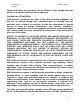
EMS Wireless EkoLink II Operator’s Manual J26 NO C Alarm 1 NC NO C NC Pin 1: ALARM-1-NO 2 Amp Max Load Current Pin 2: ALARM-1-C Audible Buzzer (Alarm Indicator) Pin 3: ALARM-1-NC Pin 4: ALARM-2-NO Red Light (Alarm Indicator) Pin 5: ALARM-2-C Pin 6: ALARM-2-NC Green Light (No Alarm Indicator) Typical application circuits Alarm 2 General Circuit Topology Figure 18: Application of Alarm Relay Contacts 4.8.2.
EMS Wireless EkoLink II Operator’s Manual +5VDC ** - Use R to limit current to 20mA J27 R Pin 1: V-ALARM Pin 2: ALARM-OC Pin 3: GND Pin 4: Not Connected Alarm N/C Pin 5: EXT-ALARM-1-IN uCont Pin 6: ALARM-2-NC General Circuit Topology Typical Application Circuit Figure 19. J27 Application, Single Hub using internal supply voltage. The Hubs may also be configured in an OR configuration as seen in Figure 12. External alarm circuitry must be current limited to 20mA.
EMS Wireless EkoLink II Operator’s Manual 5.0 Troubleshooting Guide The chief indicator of a failure is the Status LED located on each of the Remotes and the Hub. The user can ascertain the nature of the failure by either logging into the Hub and invoking the Alarm command or by using Tables 12 and 13 below. Under normal operating conditions, these LEDs will be solid green. If an alarm condition occurs, the LEDs will indicate the nature of the failure and assist the user in deciding on a coarse of action.
EMS Wireless EkoLink II Operator’s Manual 5.2.1 Internal Alarms The Internal Hub Alarms are described in Table 13.
EMS Wireless EkoLink II Operator’s Manual APPENDIX A Terminal Communications The EkoLink II can be configured and monitored via direct serial RS-232 connection. The following paragraphs describe in detail how to connect to the Hub. Direct Terminal Connection The EkoLink II Hub can be controlled via standard RS232 Communications port located on the front of the Hub chassis. A laptop computer is recommended for system setup and verification.
EMS Wireless EkoLink II Operator’s Manual A dialog box will ask you to name the session. Use any name you choose. For this example, the name EkoLink II was used. Select the icon showing the two telephones as shown in Figure A-1. 3. Figure A-1. Connection Description in HyperTerminal 4. For a direct connection to the repeater, choose “Direct to Com X” in the drop down box in Figure A-2. Figure A-2. HyperTerminal Screen for Direct Connection.
EMS Wireless EkoLink II 5. Operator’s Manual After clicking OK, you will need to choose “Port Settings.” Select: • • • • • Bits per Second: 9600 Data bits: 8 Parity: None Stop bits: 1 Flow control: None Figure A-3. Port Settings for Direct Connection and Remote Connection The port settings will be the same for direct connection and remote connection, except for the flow control. For a direct connection to the repeater, make sure flow control is set to “None.
Installation Guide EkoLink II Fiber Optic Distributed Antenna System 608577-2 Rev A 7 August 2003 2850 Colonnades Court Norcross, GA 30071 U. S. A. Tel: +1 770.582.0555 Fax +1 770.729.
EMS Wireless EkoLink II Operator’s Manual 1.0 Installation Guide The following guidelines provide a step by step installation procedure which should be followed closely to insure a successful deployment. 1.1 Shipment Contents The following items should be included with each EkoLink II Shipment: Hub(s) Remotes(s) User manual (this document) Software Command Reference Manual AC Power supply (optional) 1.2 Site Selection 1.2.1 Hubs The Hub(s) should be located as close as possible to the donor BTS.
EMS Wireless EkoLink II Operator’s Manual In this section, instructions are provided for organizing the system layout before installation. The installer or operator must make sure that certain requirements have been met before beginning installation. In addition, all cables and fibers must be labeled, and the entire system configuration must be documented. Steps for this pre-installation set-up are given below.
EMS Wireless EkoLink II Operator’s Manual 1.5 Single Hub Installation To Install the Hub, locate it as close as possible to the Service Provider’s BTS. Any distance between the BTS and Hub will result in unnecessary cable losses. It is also very important to ensure that the composite RF Downlink power does not exceed +20 dBm. Table 1 shows the maximum allowable power setting for each carrier to arrive at a composite power of +20 dBm. Number of Carriers 1 2 3 4 n Power Per Carrier +20 dBm +17 dBm +15.
EMS Wireless EkoLink II Operator’s Manual • Install the Slave Hub(s) using a Philips screwdriver and the provided screws, secure the Hub(s) in a standard 19” equipment rack near the Master Hub • Using SMA cables, connect the Slave Downlink Outputs on the rear of the Master Hub to the Slave Downlink Inputs on the Slave Hub(s) • Using SMA cables, connect the Slave Uplink Inputs on the rear of the Master Hub to the Slave Uplink Inputs • If purchased, connect a standard RJ-45 phone cable to the Master Alarm C
EMS Wireless EkoLink II 1.9 Operator’s Manual System Verification and Initialization If all the previous steps have been followed carefully, the EkoLink II system is now ready for verification and initialization. Connect to the Hub via serial cable or modem. Note that if no master controller is present, the user will connect to the “HUB RS232” connector located on the rear of each Hub.
EMS Wireless EkoLink II Operator’s Manual When the Hub Controller first powers up, there is a start-up message indicating the firmware release and copyright legends: Hub Controller Program V0.99 [Build 04Oct02] Copyright (c) 2002, EMS-Technologies, Inc. If the user presses the ENTER key, the login prompt is displayed: Hub Controller Program V0.99 [Build 04Oct02] Copyright (c) 2002, EMS-Technologies, Inc. Username: There are two basic types of login available to the customer; guest, and user.
EMS Wireless EkoLink II Operator’s Manual flash on power-up. If the check value does not agree, then the default settings are used. 2.9.2 Command Structure There is an extensive user help menu available to the user and a separate software command reference manual. The basic format for all the commands is: = All commands are made up of this generic format; in some cases, there is no setting or secondary command.
EMS Wireless EkoLink II Operator’s Manual where n corresponds to the desired channel. 2.9.4 Offsets Under normal conditions, the factory default power settings are configured to provide +20 dBm output power at each remote. The factory settings will provide optimum performance in most environments; however the user has the option to change the power settings in each remote according to individual requirements. Set an “offset” to the default value for the desired remote.