
User's Manual


EMS Wireless Operator’s Manual
EkoLink Plus Fiber Optic DAS
22
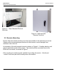
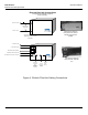
OPTICS
Output
Input
Optical RX
DC
Laser
EKO-LINK PLUS
1.9 GHz
800 MHz
RS-232C Serial
Modem
DC
Input
Alarm Output
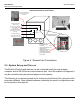
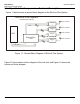
EkoLink Plus Hub Connections
Single Mode Fiber
Optic Cables
Remote 1 Downlink
Remote 1 Uplink
TX
TX
RX
RX
1.9 GHz BTS Uplink
1.9 GHz BTS Downlink
800 MHz BTS Uplink (Optional)
800 MHz BTS Downlink (Optional)
Local Maintenance Computer Connection
Telephone
Connection
(RJ11
Conector) for
Remote
Alarming
24 VDC
Power (120
VAC
optional)
External
Alarm
Circuitry
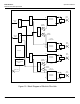
(Configured without WDM, and without
Receive Diversity)
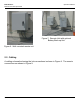
Typical EkoLink Plus Hub
front panel shown with two
RF/Optical Transceivers
Installed
Typical EkoLink Plus Hub
Rear Panel with 1900 MHz
only
(Hub shown with one remote.
Additional remotes are wired
identically.)
Figure 8: EkoLink Plus Hub Cabling Connections