
User's Manual


EMS Wireless Operator’s Manual
EkoLink Plus Fiber Optic DAS
23
3.0 System Set-up and Turn-on
The EkoLink Plus hub and remotes can be configured locally through a laptop
computer and its RS-232 serial communications port. Once the system is configured, it
can be controlled using an optional telephone line interface.
The following is a summary procedure for configuring the EkoLink Plus using its built-in
automatic software. More detailed software commands for specific configurations can
be found later in this manual.
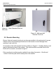
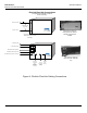
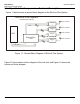
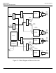
EkoLink Plus Remote Connections
Fiber
AC MainAntenna
Div RX Ant
Single Mode Fiber Optic
Cable(s) to Hub
AC or DC Power (depending
on option), or Battery Backup
Unit (optionally)
TX/RX Server Antenna [N(f)
connector with 1/2" coax]
Diversity Receive Antenna
(optional) [N(f) connector with
1/2" coax]
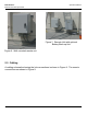
Fiber Optic Connections
Inside Remote Unit
y Install FO jumper with single
FC connector to FO
transceiver.
y Fusion splice jumper to FO
cable from hub.
y Repeat for diversity RX
connection, if used.
y Use optional pull box to
protect splices and coil up
excess cable.
(See Optional Battery Backup
Instructions for Detailed
Connections)
Chassis Ground Screw
Figure 9: Remote Unit Connections