
User's Manual


EMS Wireless Operator’s Manual
EkoLink Plus Fiber Optic DAS
28
5.0 Major Modular Components – Technical Description
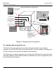
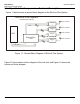
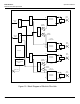
Figure 11 below shows a general block diagram of the EkoLink Plus System.
Figure 12 below shows a block diagram of the hub unit, and Figure 13 shows the
remote unit block diagram.
DL +20 dBm
BTS
EkoLink Plus
Hub
UL
UL
UL
UL
UL
DL
Fiber
Coaxial Cable
DL
DL
DL
Server Antenna 1
Server Antenna 2
Server Antenna 3
Server Antenna 4
Remote
1
Remote
2
Remote
3
Remote
4
EkoLink Plus System
(Simplified Block Diagram)
Figure 11: General Block Diagram of EkoLink Plus System