
User's Manual


EMS Wireless Operator’s Manual
EkoLink Plus Fiber Optic DAS
30
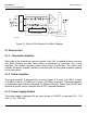
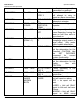
5.1 Remote Unit
5.1.1 Channelizer Modules
Each path in the channelizer module consists of an LNA, a baseband down converter
with SAW (Surface Acoustic Wave) filters, a baseband up converter, and a post
amplifier. The module includes power level control functionality. The uplink path
includes the power amplifier, while the downlink path has the power amplifier external
to the channelizer.
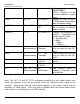
5.1.2 Power Amplifier
The power amplifier is designed for an output power of 2 watts (+33 dBm), 4 watts
(+36 dBm), 8 watts (+39 dBm) or 20 watts (+43 dBm) composite. The power amplifier
is designed to meet industry standards for Adjacent Channel Power Ratio (ACPR) and
spectral re-growth, and is compliant with all FCC required standards.
5.1.3 Power Supply Module
The power supply is designed for an input voltage of +26VDC or optionally 90 – 130
VAC, or 187 - 265 VAC.
Filter
AMP
MI XER
SAW Fil. MIXER
AMP
Filt er
AMP
Power
Amp
CONTROLLER
Wireless or
Wired Modem
RS 232/
Tec h Port
Duplexer
Fiber Optic
Transceiver
Fiber
Input
Fiber
Output
WDM
Fiber
In/Out
Optional
Channelizer Module
(Optional)
Tel co
Line
RS 232/
Programming
(Simplified Block Diagram)
EMS Wireless
Figure 13: EkoLink Plus Remote Unit Block Diagram