SYSTEM 7000 7940 HIGH POWERED UHF CONTACT OPERATED TRANSMITTER INSTALLATION AND PROGRAMMING INSTRUCTIONS
EMS 7000 IRIS + Table of Contents Section Page No 1. INTRODUCTION............................................................................................................. 3 2. TOOLS & TEST EQUIPMENT............................................................................................. 3 3. EQUIPMENT REQUIRED: ................................................................................................. 4 4. PROGRAMMING CONNECTION DETAILS .....................................................
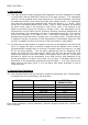
EMS 7000 IRIS + 1. Introduction 1.1 The high powered contact operated UHF transmitter has been designed to operate in conjunction with the EMS IRIS 7256 and 7703 radio receivers. The transmitter unit is a 12 volt operated device and comprises of a 500mW transmitter, fitted with an additional printed circuit board with eight opto isolated inputs. The transmitter only uses four of these opto isolated inputs; these are inputs 1, 2, 7 and 8. These inputs when activated transmit fixed events.
EMS 7000 IRIS + 3. Equipment Required: 7940 Contact Operated Transmitter 7256 IRIS Receiver with standard 7200 software or 7703 Receiver Power Supply Units Windows HyperTerminal with serial lead if programming changes are required. 3.1 Remote devices and high gain aerials may also be required for range extension, depending upon the customer’s specification and requirements.
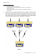
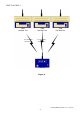
EMS 7000 IRIS + 7940 Half Watt Txer Four Input Data Transmissions 7940 Half Watt Txer 7940 Half Watt Txer Four Input Data Transmissions 7703 Rxer Figure 2 7940 ENGINEERS GUIDE v2.
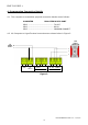
EMS 7000 IRIS + 4. Programming Connection Details 4.1 The computer to transmitter physical connection details are as follows:COMPUTER ISOLATED RS 232 PORT PIN 2 ---------------------------------- TX OUT PIN 3 ---------------------------------- RX IN PIN 5 ---------------------------------- COMMON CONNECT 4.2 All Computer to HyperTerminal connections are shown below in Figure 3.
EMS 7000 IRIS + 5. Transmitter Programming 5.1 The transmitter unit has the facility of changing it’s inputs orientation and also the unique identity code for the transmitter can be programmed. The settings for the transmitter are as follows with the menu commands required shown in brackets:Inputs unique identification code (ID). Orientation of the input to normally open or normally closed (CON).
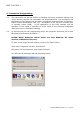
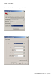
EMS 7000 IRIS + Now enter your desired connection description: - Then click on the ‘OK’ button, and the screen will change to the following: - 7940 ENGINEERS GUIDE v2.
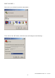
EMS 7000 IRIS + Now select the Comm Port required as below: - 7940 ENGINEERS GUIDE v2.
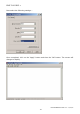
EMS 7000 IRIS + Now select the following settings: - Once completed, click on the ‘Apply’ button and then the ‘OK’ button. The screen will change to display: - 7940 ENGINEERS GUIDE v2.
EMS 7000 IRIS + Now select ‘Call’ and ‘Disconnect and the screen will change to display: - Now select ‘File’ and ‘Properties’. The screen will change to display:- 7940 ENGINEERS GUIDE v2.
EMS 7000 IRIS + Now select the ‘Settings’ tab and the screen will change as below: - The Settings should be set as follows: - 7940 ENGINEERS GUIDE v2.
EMS 7000 IRIS + Once the settings are as above, click on the ‘ASCII Setup‘ button and check that the settings are as follows: - Once the settings are as above, click on the ‘OK’ button then on the next window click on the ‘OK’. We can now establish a connection by selecting ‘Call’ and ‘Call’ as below:- Once completed, HyperTerminal is configured. Please Note: To save future reconfiguration, the HyperTerminal session can be saved for future use. 7940 ENGINEERS GUIDE v2.
EMS 7000 IRIS + Once the settings are as above, click on the ‘OK’ button then on the next window click on the ‘OK’. Now Hyperterminal is configured. 5.3 To gain access to command menu press the enter key 3 times. The terminal display should change to:COMMAND id, con, txd, quit > 6. ID 6.1 The transmitter has an individual identification number, which is set from this menu. This allows the transmitter to be added into the IRIS/7703 receiver with a unique number. The default ID for the transmitter is 1846A.
EMS 7000 IRIS + 7. CON 7.1 Each of the transmitters inputs can be programmed to operate via a normally open or normally closed configuration. Note: Inputs 1, 2, 7 and 8 are only used on this device. Input 1 activating an alarm transmission, input 2 a local transmission, input 7 a low battery transmission and input 8 a tamper transmission. The default setting for all of the inputs is to normally open. Note: As the tamper input is pre-wired at the factory this setting will be changed to normally closed.
EMS 7000 IRIS + 10. Adding A Transmitter Into The IRIS Radio Receiver The following sequence of operations is required when adding a transmitter into the UHF IRIS Radio Receiver. 10.1 The IRIS LCD screen with the key in the “CLEAR” position will show the following display: System Clear 01/10/93 10.2 Turn the front panel key to “RESET”. The screen will change to display: 13:26 *** SYSTEM RESET *** 13:26 10.
EMS 7000 IRIS + 10.10 Activate the transmitters onboard tamper switch and observe the screen will display: Release all buttons NOW 16:38 10.11 After a short period of time the screen will change to display: 10.12 Using the same operation, once again generate a transmission, after a short period of time the screen will change to display: Operate Transmitter Again or press Escape to cancel 16:38 Hand Push 001 Added Push any key 16:38 10.
EMS 7000 IRIS + 11. Assigning Text Description For A Transmitter 11.1 Repeat steps 10.1 to 10.4. 11.2 Press “ ” displays: screen | Time and Date | > Radio Setup < | Output Setup | 2=Help 16: 37 11.3 Press the “1” button and the screen will change to display: | ** Radio Setup ** | > Add Transmitter < | Txer Details | 2=Help 16:37 11.4 Press “ ” and the screen will now display: | Add Transmitter | > Txer Details < | Set Radio Rules | 2=Help 16:37 11.
EMS 7000 IRIS + 11.11 By using the “4” button to move left or the “6” button to move right, move to the letter or number required and press the “5” button to select the character. 11.12 Repeat 11.11 until all letters have been selected. Once completed press the “ ” button to save the information. 11.13 Once completed you may now escape from this menu by pressing the “3” button on the keypad until the “SYSTEM RESET” message appears, or by returning the key to the “CLEAR” position.
EMS 7000 IRIS + 13. Internal Input Wiring Figure 4 7940 ENGINEERS GUIDE v2.
EMS 7000 IRIS + 7940 ENGINEERS GUIDE v2.
EMS 7000 IRIS + Dealer Information: EMS Group Head Office Technology House, Sea Street Herne Bay, Kent CT6 8JZ England Tel: +44 (0) 8712 710804 Fax: +44 (0) 1227 369679 Email: enquiries@emsgroup.co.uk The information contained within this literature is correct at time of publishing. The EMS Group reserves the right to change any information regarding products as part of its continual development enhancing new technology and reliability.