Product user manual & operation description EMV3000 Document number: 915-11135-01
Product user manual & operation description EMV3000 Document version Version Date Author Description 01 16/06/2021 Emsyscon Draft release FCC and IC compliance statement EMV3000 This device complies with Part 15 of the FCC Rules and with Industry Canada licence-exempt RSS standard(s). Operation is subject to the following two conditions: 1. This device may not cause harmful interference, and 2.
Product user manual & operation description EMV3000 Table of Contents 1 2 INTRODUCTION ..................................................................................................................................................................................7 1.1 EMV3000......................................................................................................................................................................................7 1.2 EMV3000 Key features ...................
Product user manual & operation description EMV3000 Table 4: Electronic and operation .......................................................................................................................................................... 8 Table 6: Used symbols .............................................................................................................................................................................. 11 Table 7: Safety inspection checklist ...............................
Product user manual & operation description EMV3000 Purpose This manual provides guidelines on how to install, wire and connect an EMV3000. Based on our experience, a number of recommendations are illustrated. Note that only the products that follow are within Emsyscon’s scope of delivery: ◼ EMV3000 ◼ EMV3000 mounting material (on demand) ◼ … All other devices and items necessary for installation are excluded from Emsyscon’s scope of delivery.
Product user manual & operation description EMV3000 Term Definition SAM Secure Access Module/Secure Application Module TFT Thin-Film Transistor TTL Transistor-Transistor Logic UART Universal Asynchronous Receiver-Transmitter UOM Unit of Measure UPS Uninterruptable Power Supply USB Universal Serial Bus Table 1: Terminology Document number: 915-11135-01 Page 6 | 26
Product user manual & operation description EMV3000 1 INTRODUCTION 1.1 EMV3000 The EMV3000 is a compact NFC contactless smart card reader. It is designed specifically for public transport Automatic Fare Collection (AFC) systems, but can also be used in unattended devices like vending machines, parking meters, toll gates and more. The EMV3000 supports all major smart cards compliant to ISO 14443 Type A and B. 1.2 ◼ ◼ ◼ ◼ ◼ ◼ ◼ ◼ EMV3000 Key features Contactless smart card reader 13.56 MHz NFC.
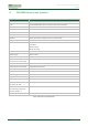
Product user manual & operation description EMV3000 1.5 EMV3000 Electronic and operation Subject Description Antenna gain <2 Audio Internal PWM beeper with the ability to drive external beeper Bandwidth 14 kHz Card reader Full NFC forum-compliant for contactless communication at 13.
Product user manual & operation description EMV3000 1.
Product user manual & operation description EMV3000 1.
Product user manual & operation description EMV3000 1.8 Used symbols A number of symbols are repeatedly used in this manual. Their meaning is indicated below. Symbol Description Meaning Attention! Pay particular attention to the work to be done. Read carefully Read this advice. Time Realistic time indication taken up by these activities. Special tooling Use the specified tooling. Danger: electricity The components may contain electrically charged or live elements.
Product user manual & operation description EMV3000 2 SAFETY INFORMATION 2.1 General safety Observe the rules that follow to ensure general safety. Remark: The information that follows is based on a wide range of hardware products. Part of this information is product specific and might not be applicable to the product(s) outlined in this manual. ◼ Observe good housekeeping in the area of the equipment during and after installation.
Product user manual & operation description EMV3000 2.2 Electrical safety Observe the rules that follow when working on electrical equipment. ◼ Use only approved tools and test equipment (GS-, IEC 60900-, VDE standards). Some hand tools have handles covered with a soft material that does not insulate you when working with live electrical currents. ◼ Many customers have, near their equipment, rubber floor mats that contain small conductive fibres to decrease electrostatic discharges.
Product user manual & operation description EMV3000 ◼ Always look carefully for possible hazards in your work area. Examples of these hazards are moist floors, not grounded power extension cables, power surges, and missing safety grounds. ◼ Do not touch live electrical circuits with the reflective surface of a plastic dental mirror. The surface is conductive; touching can cause personal injury and equipment damage.
Product user manual & operation description EMV3000 Checklist: No Description OK NOK 1 Check exterior covers for damage (loose, broken, or sharp edges) ☐ ☐ 2 Power off the equipment, disconnect the power ☐ ☐ 3 Check the power cord for (if applicable): a A third-wire ground connector in good condition, use a meter to measure thirdwire ground continuity for 0.
Product user manual & operation description EMV3000 ◼ Select a grounding system, such as those listed below, to provide protection that meets the specific service requirement. Note: The use of a grounding system to guard against ESD damage is desirable but not necessary. Attach the ESD ground clip to any frame ground, ground braid, or green-wire ground. Use the round ground prong of the AC plug on AC-operated equipment.
Product user manual & operation description EMV3000 3 GENERAL INSTALLATION GUIDELINES ◼ Before starting the installation works, make sure to disconnect the vehicle battery in order to avoid short circuits. Some vehicles may have a secondary battery or even UPS/no break power supplies for some functions. Obey at all times the instructions of the vehicle manufacturer and vehicle owner. ◼ Respect at all times the safety guidelines and use the right tooling.
Product user manual & operation description EMV3000 4 INSTALLATION TOOLING LIST This section is a summary of the most-used tools necessary to install the EMV3000. These tools should be at the technician’s disposal to carry out normal installation work. Equivalents of this tooling can also be used by the installer/technician, this depending on availability and corresponding with the tooling technical specifications.
Product user manual & operation description EMV3000 5 INSTALLATION MATERIAL 5.1 Standard installation material This section contains the standard installation material that is delivered with the EMV3000. Optional, any specific and/or additional installation material can be delivered by Emsyscon upon request (see section 5.2). Article n° Qty UOM Description Image Reference N/A Table 8: Standard installation material 5.
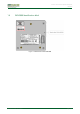
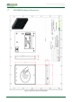
Product user manual & operation description EMV3000 6 INSTALLATION INSTRUCTIONS 6.1 EMV3000 mechanical integration 1. The EMV3000 back shell contains 3 mounting holes (3 inserts M2.5) (Figure 4). These mounting holes can be used to fix the EMV3000 to a mounting frame. Mounting frames are project specific but can be ordered at Emsyscon. The maximum screw length mounted into the EMV3000 is 6mm. This based on a mounting frame with 2mm thickness.
Product user manual & operation description EMV3000 2. The EMV3000 is mounted with 3 screws (reference D02) and 3 spring lock washers (reference D03) on the mounting frame (Figure 5). Torque setting screwdriver: 40 N.cm D02 Mounting frame (example) D03 T02 T01 Figure 4: Mount EMV3000 6.2 EMV3000 Cable connection(s) Always integrate a cable strain relief when connecting the EMV3000. This to avoid bad connections and loss of data and power connection over a period of time. 6.2.
Product user manual & operation description EMV3000 6.2.2 Connection via 16-way connector This type of connection is only used in case of a printed circuit assembly (PCA) integration (Figure 7). Example of an EMV3000 integrated via a PCA (Figure 7).
Product user manual & operation description EMV3000 6.3 EMV3000 Cable connection diagram(s) 6.3.1 Micro-USB connection diagram Micro USB connection Connection PIN 1 +5V 2 USB0B_N 3 USB0B_P 4 Not connected 5 GND (SHLD) Table 10: Pin layout micro-USB connection 6.3.
Product user manual & operation description EMV3000 7 EMV3000 IN OPERATION 7.1 Standard operation modus When powering on the EMV3000, the device will boot and start up. After maximum 10 seconds the device is ready for use. Once the start-up process is finished, the EMV3000 LED 1 will blink once every 5 seconds. The EMV3000 is now in normal operation and the contactless card reader is ready to use.
Product user manual & operation description EMV3000 8 EMV3000 ERROR STATUS 8.1 EMV3000 Tamper status (1) error Period Time (s) LED 1 LED2 LED3 LED4 1 3 ON OFF OFF OFF 2 3 OFF ON ON ON Period 1 and 2 repeats Figure 8: Tamper status (1) error 8.
Product user manual & operation description EMV3000 8.3 EMV3000 Boot error Period Time (s) LED 1 LED2 LED3 LED4 N/A N/A OFF OFF OFF ON Figure 10: Boot error 8.4 EMV3000 Start-up error Period Time (s) LED 1 LED2 LED3 LED4 N/A N/A OFF OFF ON ON Figure 11: Start-up error End of document.