
User guide


6
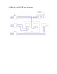
“+” (pin 3), and the “-“ (pin 2) to the “-“ (pin 4), when output port 5 on the
DSP is triggered. This is typically used to switch speaker level signals, so
an overflow room can be fed directly from an amplifier without needing its
own dedicated amplifier channel.
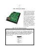
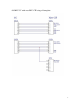
Connecting the BLU-CIF to the BSS Audio London Series DSP
The BLU-CIF ships with two pre-fabricated 12-conductor cables. Each
cable has 3.5mm connectors on both ends. On one end, the 3.5mm
connectors are color-coded green and black, so they match up with either the
Control Port 1 (Black) connector or Logic Inputs (Green) connector on the
upper right quadrant of the CIF Board.
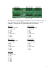
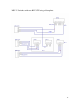
Control Inputs Connector
Logic Outputs Connector
Control Inputs connector mates with the cable
with Control_Port1 (Black) connector.
Logic Outputs connector mates with the cable
with Logic Inputs (Green) connector.