
Instruction Manual


3
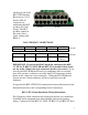
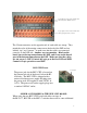
8-pins, and are located behind the RJ-45 blocks on the top half of the board
for DSP1, and on the bottom half of the board for DSP2 .
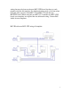
BLU-CP1 BLU-CS/SV1 BLU-SV2
BLU-CC2A/SV5 BLU-CC2B/SV6 BLU-SV7
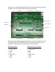
The legends for identifying and wiring these euro-style connectors have all
been silkscreened on the CIF2 Board at the top and bottom side of each
connector. The pin-outs for each connector are listed below:
BLU-CP1 & CP2
BLU-CS1/SV1 & CS2/SV3
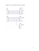
1. Power Button (IN1) 1. Power Button (IN3)
2. Volume (IN2) 2. Volume (IN4)
3. VCC 3. Ref
4. +24V 4. N/A
5. Ref 5. VCC
6. LED (OUT1) 6. LED (OUT2)
7. GND 7. GND
8. GND 8. GND
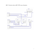
BLU-CC1A
BLU-CP2
BLU-CC1B
BLU-CS2/SV3
BLU-SV4