
Instruction Manual


5
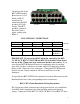
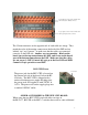
There are no switches associated with the C switch connectors on the new
version of CIF2 board. IN11 and IN12 are bit encoded with 4 bits each. C-
SW1 and C-SW2 map to IN11, and C-SW3 and IR4-5 map to IN12. When
either a C switch or IR get wired to the CIF board, the device will be
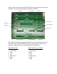
automatically detected. The pin-outs on the C switch connectors are:
C-SW1 thru 3
1. +24V
2. SW1
3. SW2
4. Common
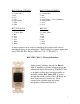
USING the C-SW INPUTS WITH BLU-IR INFRARED SENSORS
The BLU-IR Infrared Sensors can be wired to the 4-pin C-Switch euro-style
connectors. Wire each IR sensor to its’ corresponding 4-pin connector using
this pin-out:
C-SW1 thru 3
1. Red
2. Green
3. N/A
4. Black