
Instruction Manual


6
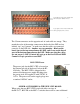
BLU-CIF2 PWR RELAY & OF RELAY Wiring Instructions
The voltage from the +24 pin is typically connected to an external power
relay coil, which will then switch 120VAC on to the external equipment.
The PWR RELAY output is thermo-fuse protected, so it will stop supplying
power when the +24 pin exceeds 100mA. The circuit will reset
automatically once the load is disconnected.
The 4-pin OF_1 & OF_2 overflow relay connections are 2-pole “dry
contacts” that are normally open. These contacts will close connecting the
“+” (pin 1) to the “+” (pin 3), and the “-“ (pin 2) to the “-“ (pin 4), when
output port 5 on the DSP is triggered. This is typically used to switch
speaker level signals, so an overflow room can be fed directly from an
amplifier without needing its own dedicated amplifier channel.
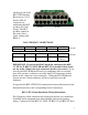
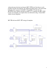
Connecting the BLU-CIF2 to the BSS Audio London Series DSP
The BLU-CIF2 ships with four pre-fabricated 12-conductor cables. Each
cable has 3.5mm connectors on both ends. On one end, the 3.5mm
connectors are color-coded green and black, so they match up with either the
Control Port 1 for DSP 1 & Control Port 2 for DSP 2 (Black) connector or
the Logic Inputs (Green) connectors for DSP1 & DSP2 on the far right side
of the CIF2 Board.
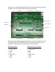
Control Inputs Connector
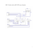
Logic Outputs Connector
There are four separate relay
connectors on the right side of the
CIF2 board. The 2-pin PWR_1 &
PWR_2 connections are used to
power on external equipment. This
connection will supply +24VDC @
100mA on the “+24” pin when logic
out
p
ut 6 on the DSP is tri
gg
ered.