
Instruction Manual


7
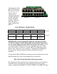
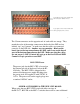
The 3.5mm connectors on the opposite end of each cable are orange. They
match the color of the mating connector on the back of the DSP and are
labeled “top” and “bottom”, so make sure that the cables are connected
correctly on the DSP side. Another way to remember : Black on the
board goes to the top connection on the DSP, and Green on the board
goes to the bottom connection on the DSP. Make sure that the cables
are not crossed – DSP1 Control & Logic go to the first DSP and DSP2
Control & Logic go to the second DSP.
BLU-CIF2 Power
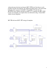
OLDER ACCESSORIES & THE NEW CIF2 BOARD
When using the new BLU-CIF2 board with older versions of
the BLU-CC, BLU-IR or the MSC-C switches there will be some additional
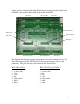
Control Inputs connector mates with the cable
with Control_Port1 (Black) connector.
Logic Outputs connector mates with the cable
with Logic Inputs (Green) connector.
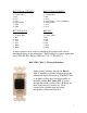
Power Jack
The power jack for the BLU-CIF2 is located on
the bottom left side of the board; below the RJ-
45 blocks. The BLU-CIF2 is shipped with a
universal desktop power supply that plugs into
the power jack, and supplies it with 24VDC @
1.67A. The power cord on the supply plugs into
a standard 120VAC outlet.